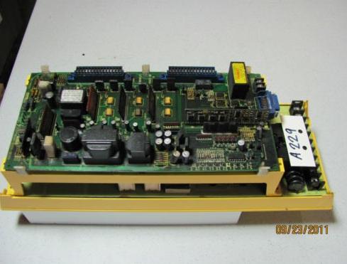
A06B-6058-H005: Beyond the User Manual

A06B-6058-H005: Beyond the User Manual

Generally, Fanuc AC servo motors, like the A06B-6058-H005, have no parts that wear off or that must be replaced periodically, unlike DC servo motors, which have brushes that must be replaced. However, you should perform period maintenance for servo motors so as to keep their initial performance as long as possible and to prevent breakdowns. AC servo motors have precision sensors — their incorrect use or damage caused during transportation or assembling can result in breakdowns or accidents.

It is recommended that you inspect servo motors periodically, and of course we offer a 12 month warranty on all Fanuc products purchased from MRO Electric.

Receiving and Keeping the A06B-6058-H005

When you receive a A06B-6058-H005 module from MRO Electric, make sure that the motor is exactly the one you ordered, in terms of model, shaft, and sensor specifications, and make sure that no damage has been caused on the motor. Servo motors should be kept indoors as a rule. The storage temperature range is -20 to +60 Celsius. Do not place or install AC servo motors in a place where it is extremely humid and dew is prone to form, where there are steep changes in temperature, where there is constant vibration, or there is lots of dust and trash. Constant vibration may cause damage to the shaft bearings.

Daily Inspection Procedures

Before starting operation, or periodically (once a week or month), you should inspect the AC servo motors for vibration and noise, outside damage, stains and smudges, overheating.

Check the motor for abnormal vibration by hand, and noise by ear when the motor is not rotating, rotating at low speed, and accelerating and decelerating.

Check the Pulsecoding cover (read plastic) for crevices and the motor surface (black coating) for scratches and cracks. If you find a crevice on the Pulsecoder cover, you should replace it. If there is a scratch or a crack on the motor surface, the user should repair it by himself as required. If coating has come off, dry the portion of interest or the entire surface and coat it with paint for machines such as urethane paint.

Check the motor surface and bolt holes for oil or cutting fluid. Wipe off oil and cutting fluid on the surface periodically. Oil or cutting fluid can damage the coating by chemical reaction, possibly leading to failure. Also check how such liquid leaks onto the motor, and repair if needed.

Check to see if the motor is too hot during normal operation. Attach a thermolabel on the motor surface and check it visually to see if the motor becomes too hot during normal operation.

Visit our A06B-6058-H005 product page for more information, or to request a quote email sales@MROElectric.com or call 1-800-691-8511
a06b-6058-h005
a06b-6058-h005

Fanuc Motor Safety Procedures and Tips

We have people ask about best practices for working with Fanuc motors all the time, so here are some Fanuc Motor Safety Procedures and Tips. For more info you can check out  all of our Fanuc products or email us at sales@mroelectric.com.
When working with servo motors:
•NEVER pick up or carry the motor by the cables or the shaft. (Always carry by the frame.) Use a crane or lift to move the motor when necessary.
•NEVER drop or subject the motor to impact. The servo motor is a precision device.
•NEVER set heavy or sharp objects on the motor or cables. Do not step or sit on the motor or cables.
•NEVER use a metal hammer on any part of the motor. If it is absolutely necessary to use a hammer, use a plastic hammer.
Keep the motor properly secured and away from the edge of the work area when servicing the motor, as a dropped motor could

cause personal injury or destroy the motor

Basic Motor Safety, Procedures, and Best Practices
• Be safely dressed when handling a motor.
Wear safety shoes and gloves. Avoid loose clothing which can get caught
on the motor. Be careful not to let hair get caught in the rotary section of the motor. Do not handle the motor with wet hands.
• Shut off the power before working on a motor. Wait at least 5 minutes after the motor is shut off before touching any
power terminals.
• Always use the correct cables. Centroid cables are shown in the motor compatibility table. Wiring diagrams and pin outs
for motors are provided in Appendix B.
• Ensure that the motor and motor related components are mounted securely. Ensure that the base or frame to which the
motor is mounted to is strong enough.
• Do not touch the rotary section of the motor when it is running unless instructed to.
• When attaching a component having inertia to the motor, ensure any imbalance between the motor and component is minimized.
• Be sure to attach a key to a motor with a keyed shaft.
• Use the motor in appropriate environmental conditions. Do not store flammables in close proximity to the motor. When
not in use, store the motor in a dry location between 0° to 40° C.
• Do not remove the nameplate from a motor

Upgrading From FANUC C Series Servo Amplifier to α Series

If you experience a system failure due to a Fanuc C series servo amplifier, (A06B-6066-H002, H003 etc.) you may feel like your only option is to replace it with the same exact unit. However Fanuc also offers the α series servo amplifiers which features improvements over the C series. In most cases you can replace your C series servo amplifier with the α series servo amplifier that has the identical final four numbers of the C series model number. The chart below outlines this:

The advantages of replacing your C series amplifier with an α series amplifier are:

  • A built in power supply
  • A second interface, type B, as well as the more conventional type A interface
  • Updated power device, intelligent power module, to reduce power loss and increasing reliability

α series amplifiers are also designed with the same dimensions as the C series so that you can install them into your current system easier.

Go to our website to check out our selection of C series and α series FANUC amplifiers.

A06B-6117-H211 Alarm Code Troubleshooting

 List of A06B-6117-H211 Alarm codes that should help you with troubleshooting. If you do decide you need more help or want to replace your unit, give us a call at 800-691-8511 or email sales@mroelectric.com. You can also visit our product page for the A06b-6117-H211 for more info, or check out all of our FANUC motors and drives.
Alarm Code 1
      (1)Meaning Inverter: internal cooling fan stopped
      (2)Cause and troubleshooting
              (a)Check whether there is any foreign material in the fan.
              (b)Check that the fan connector is attached correctly.
              (c)Replace the fan.
              (d)Replace the SVM.
Alarm Code 2
     (1)Meaning Inverter: control power supply under voltage
     (2)Cause and troubleshooting
              (a)Check the three-phase input voltage of the amplifier (the voltage shall not be lower than 85% of the rated input voltage).
              (b)Check the 24 V power supply voltage output from the PSM (the voltage shall normally not lower than 22.8 V).
             (c)Check the connector and cable (CXA2A/B).
             (d)Replace the SVM.
Alarm Code 5
      (1)Meaning Inverter: DC
link under voltage
      (2)Cause and troubleshooting
              (a) Check that the screws for the DC link connection cable (bar) are tight.
              (b)If a DC link low voltage alarm condition occurs in more than one module, see Subsection 3.1.4, “Alarm code 4” for explanations about how to troubleshoot the power supply module.
              (c)If a DC link low voltage alarm condition occurs in only one SVM, replace that SVM.
Alarm Code 6
     (1)Meaning Inverter: overheat
     (2)Cause and troubleshooting
            (a)Check that the motor is being used at or below its continuous rating.
            (b)Check that the cooling capacity of the cabinet is sufficient (inspect the fans and filters).
            (c)Check that the ambient temperature is not too high.
            (d)Replace the SVM.
Alarm Code F
     (1)Meaning Inverter: cooling
fan stopped of the radiator
     (2)Cause and troubleshooting
          (a)Check whether there is any foreign material in the fan.
          (b)Check that the fan connector is attached correctly.
          (c)Replace the fan.
          (d)Replace the SVM.
Alarm Code P
     (1)Meaning Communication error between amplifier and module
     (2)Cause and troubleshooting
          (a)Check the connector and cable (CXA2A/B).
          (b)Replace the control printed-circuit board.
          (c)Replace the SVM.
Alarm Code 8
     (1)Meaning Inverter: DClink current alarm
     (2)Cause and troubleshooting
           (a)Disconnect the motor power leads from the SVM, and release the SVM from an emergency stop condition.
              <1>If no abnormal DC link current alarm condition has occurred. Go to (b).
             <2>If an abnormal DC link current alarm condition has occurred. Replace the SVM.
          (b)Disconnect the motor power leads from the SVM, and check the insulation between PE and the motor power lead U, V, or W.
                 <1>If the insulation is deteriorated. Go to (c).
                 <2>If the insulation is normal. Replace the SVM.
         (c)Disconnect the motor from its power leads, and check whether the insulation of the motor or power leads is deteriorated.
                <1>If the insulation of the motor is deteriorated. Replace the motor.
                <2>If the insulation of any power lead is deteriorated. Replace the power lead.
Alarm Code 8.9.A.
     (1)Meaning Inverter: IPM alarm
     (2)Cause and troubleshooting
             (a)Disconnect the motor power leads from the SVM, and release the SVM from an emergency stop condition.
                   <1>If no IPM alarm condition has
occurred. Go to (b).
                   <2>If an IPM alarm condition has occurred. Replace the SVM.
            (b)Disconnect the motor power leads from the SVM, and check the insulation between PE and the motor power lead U, V, or W.
                   <1>If the insulation is deteriorated. Go to (c).
                   <2>If the insulation is normal. Replace the SVM.
            (c)Disconnect the motor from its power leads, and check whether the insulation of the motor or power leads is deteriorated.
                   <1>If the insulation of the motor is deteriorated. Replace the motor.
                    <2>If the insulation of any power lead is deteriorated. Replace the power lead.
Alarm Code 8.9.A.
     (1)Meaning Inverter: IPM alarm (OH)
     (2)Cause and troubleshooting
             (a)Check that the heat sink cooling fan is running.
             (b)Check that the motor is being used at or below its continuous rating.
             (c)Check that the cooling capacity of the cabinet is sufficient (inspect the fans and filters).
             (d)Check that the ambient temperature is not too high.
             (e)Replace the SVM.
Alarm Code bcd
       (1)Meaning Abnormal inverter motor current
       (2)Cause and troubleshooting
              (a)Checking the servo parameters Referring to “FANUC AC SERVO MOTOR i series Parameter Manual (B-65270EN),” check whether the following parameters have default values.
Fanuc-15i PRM 1809, 1852, 1853
Fanuc-16i/18i/21i PRM & Power Mate i No.2004, 2040, 2041
For more help or a quote to replace your unit, give us a call at 800-691-8511 or email sales@mroelectric.com.

Fanuc A06B-6050-H103 Servo Jumper Settings

When replacing a Fanuc A06B-6050-H103 Servo unit you should check to make sure the replacement servo has the same top board, part number A20B-1000-0560. After this part number there will be a “/” and then something similar to “05A” which denotes the revision of the board. Ideally you would match your original unit with a replacement unit that has the same board, but if that’s not possible then all you would need to do is reconfigure the jumpers on the board. The table below shows how to get this set up so you can get your servo back up and running right away. Search for more FANUC motors/drives on our website.

MRO Electric and Supply maintains a comprehensive stock of new and used FANUC CNC and FANUC Robots parts. If you need a FANUC replacement part, please call 800-691-8511 or email sales@mroelectric.com.

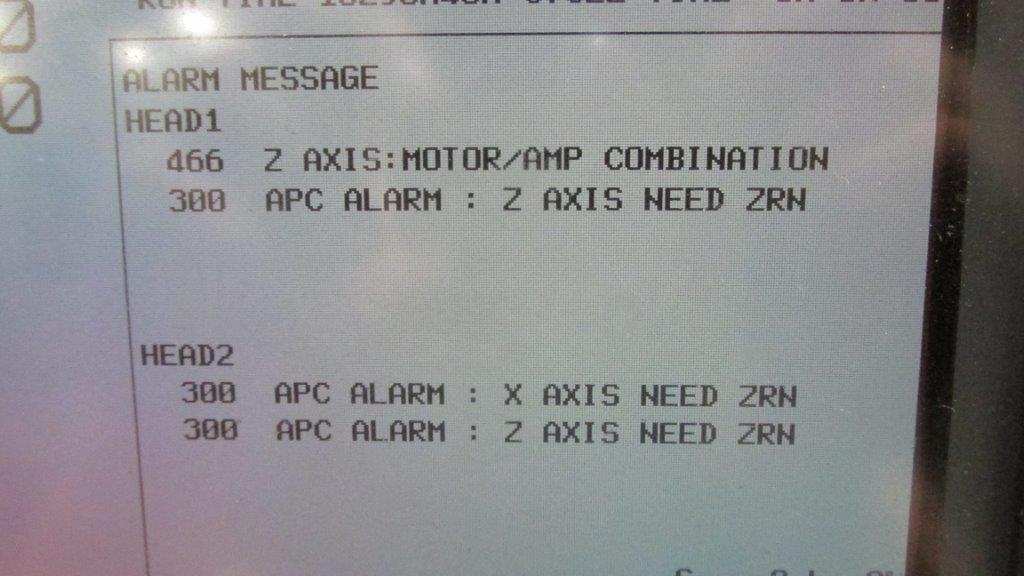
Fanuc Alarm 466 – Z Axis: Motor/Amp Combination

We just shipped out a Fanuc A06B-6096-H207 Servo Amp unit to a customer, and as soon as they installed the amplifier they got a Fanuc Alarm 466 which refers to the Z Axis: Motor/Amp Combination. This is obviously somewhat distressing for a customer to buy a replacement unit and immediately get an alarm when it is installed, but fortunately this is an easy fix.

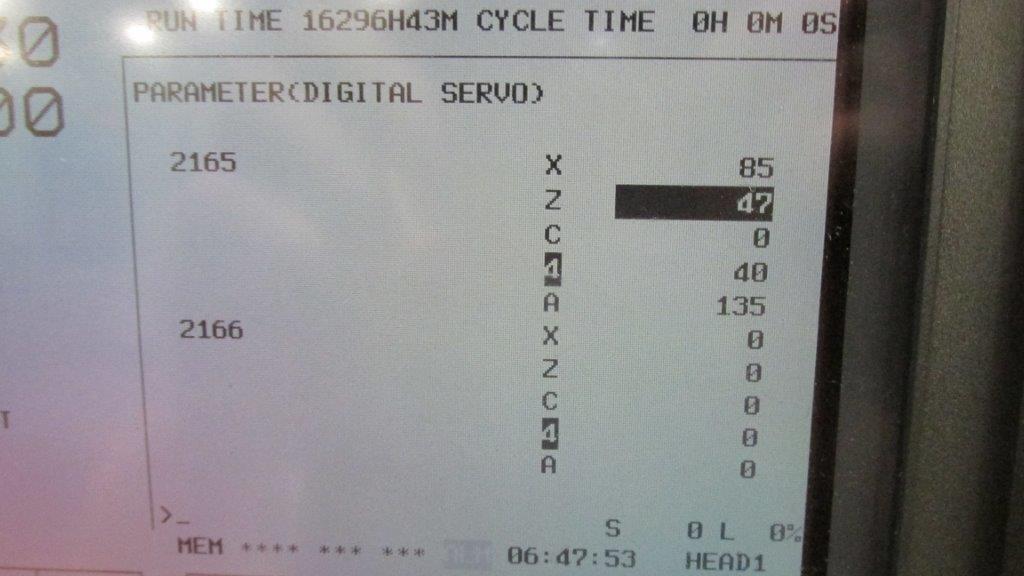
This Alarm 466 comes from the replacement amplifier having newer servo software than the unit that it is replacing. As Fanuc has made newer units they’ve upgraded the software/hardware within these amplifiers, so you just need to reset a parameter to reboot the configuration and clear the 466 Alarm. The steps are below.

– Put the machine in Emergency Stop
– Go to parameter 2165 on the control
– Set all the values to 0
– Take the machine out of emergency stop

Once these parameters are changed and the machine is rebooted, the alarm will clear and the amplifier will initialize. We also have pictures below to confirm that you know what to look for. For any additional help, call us at 800-691-8511 or email sales@mroelectric.com.

FANUC Alarm 466
FANUC Alarm 466
FANUC Alarm 466
FANUC Alarm 466
MRO Electric stocks a large number of FANUC CNC Products, and provides repair services as well. For more information or to request a quote, please call 800-691-8511 or email sales@mroelectric.com.

Fanuc A06B-0075-B503 Motor Product Video

Here is a video of one of the many Fanuc AC motors that we have in stock,  and this one is the Fanuc A06B-0075-B503 Motor. This is an AC Fanuc motor that has a brake and a keyway already installed. At 22.85lbs and 8.1 X 15.3 X 6.5 inches, this is one of the smaller motors that Fanuc manufactures. The motor in the video is brand new and comes in the original factory packaging, we only took it out of the packaging to get a video of it. If you are looking to get your old motor repaired, we do also offer a repair service for these AC motors with a standard turnaround of 3-5 days.

If you’re also trying to figure out if your motor is bad you can check out this other blog post that we put up to show some basic steps for testing your motor. The page is here, it has some useful steps to go through to confirm that your motor is causing your problem.

MRO Electric and Supply maintains a comprehensive stock of new and used FANUC CNC and FANUC Robots parts. If you need a FANUC replacement part, please call 800-691-8511 or email sales@mroelectric.com.