Determining if your FANUC Motor has a Keyway

There are a couple ways to figure out if your FANUC motor has a keyway:

The first is if you can visibly look at the end of the shaft and see the holes on the end of the coupling. If your shaft has one hole at the end in the very center, it is a slick shaft. If the shaft has three holes in a line, that means you have a keyed shaft.

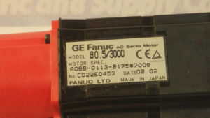
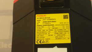
Another way to check if you have a keyed shaft without being able to look at the shaft is reading the OEM label on the FANUC motor. Your motor may have one of two types of labels on it, the first being a yellow FANUC sticker and the other being a silver G.E. FANUC sticker. All of the silver G.E. FANUC stickers on motors have a # suffix indicating a keyed shaft, except for the tag #7000 which indicates that it is actually a slick shaft. The pictures below show what each tag looks like with the # tag.

ge-fanuc

fanuc

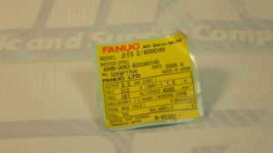
The yellow FANUC sticker is a little bit easier to determine. If the part number has the # tag at the end of it, it is a keyed shaft. If there is no # at the end of the part number, that means it is a slick shaft. Below is a picture of a yellow FANUC tag without the # tag.

keyed-shaft

Be sure to check out our article focused on maintaining automation machine tools. Maintenance is unavoidable and compiling maintenance with unnecessary rebuilds is unpractical and will likely result in downtime and lost profit. We also offer top quality repair services on all drives. With a 100% guarantee 12-month warranty we will ensure you are happy with your decision to repair with MRO Electric.

MRO Electric and Supply has new and refurbished FANUC CNC parts available. We also offer repair pricing. For more information, please call 800-691-8511 or email sales@mroelectric.com.

Testing your Alpha Power Supply Module

The following is a set of instructions to help you get your Alpha Power Supply Module to read “- -” on the display and have a consistent 300 volt DC output:

  1. Turn off the power. Make sure the charge light is off before doing anything. Check for a short between the bottom and top buss bars. If there is a short, disconnect all modules until the short disappears. Once there is no short, continue.
  2. Feed a 3 phase input into L1, L2, and L3 of the the power supply. Between 200V and 220V AC for leg to leg connections and between 100V and 110V AC for let to ground connections.
  3. Feed 200V into the CX1A connector.
  4. Install a jumper onto the top/bottom pins of the grouping of 3 pins on the CX3/MCC cable coming into the power supply.
  5. Install a jumper onto the top two pins of the grouping of 3 pins on the CX4 cable on the power supply.
  6. Make sure that all screws on the PCB are tightly screwed in.

alpha-power-supply

After following this process, your power supply module should now read “- -” and have baseline voltage output. Sometimes you may not have the necessary equipment to make a diagnosis on your motor, but we do. MRO Electric and Supply offers high quality repair services on all motors and spindle drives so you don’t have to worry about it. Please take a look at our website to see all available brands and parts we can service for you. Our rebuilds for these size drives usually only take 2-3 days, which includes rebuilding the part, painting the part, and fully testing the part to ensure top quality. By getting your part back to you as soon as possible, you are able to minimize downtime, and by doing the job right you can have peace of mind knowing that your FANUC drive will now work properly and not be the reason for downtime in the future.

MRO Electric and Supply has new and refurbished FANUC CNC parts available. For more information, please call 800-691-8511 or email sales@mroelectric.com.

FANUC Alarm Codes – A06B-6066 Drives – Alarm 5

The following is a list of procedures to fix the Alarm 5 status on your drive:

  • If you are receiving the alarm after a fresh install of the drive, check to make sure all jumpers and wires are set in their correct position. You can find the location for these inside your user manual.
  • Make sure the drive is off. Check the resistances on the drive, and then test the voltage. If it has been powered up recently, you can then turn it on to check the voltage again. However, do not immediately turn it back off to check the resistances again. You must give it at least 30 minutes for the voltage to return to safe levels so that you can check again.
  • To check the voltage, you can test the DC voltage of the jumper attached between screws 17/18 and 19.
  • Using your ground on screw 19 and and the red lead on the other two screws, your reader should say anywhere from .003 to .006 volts.
  • To check the resistance, remove the jumper from screws 15/16 and then tighten the screws. Use an ohm reader to make sure the resistance isn’t OPEN.
  • Check the resistance between screws 17 and 18. If it is 16 ohms that is where you want it to be.

fanuc cnc

Sometimes you may not have the necessary equipment to make a diagnosis on your motor, but we do. MRO Electric and Supply offers high quality repair services on all motors and spindle drives so you don’t have to worry about it. Please take a look at our website to see all available brands and parts we can service for you. Our rebuilds for these size drives usually only take 2-3 days, which includes rebuilding the part, painting the part, and fully testing the part to ensure top quality. By getting your part back to you as soon as possible, you are able to minimize downtime, and by doing the job right you can have peace of mind knowing that your FANUC drive will now work properly and not be the reason for downtime in the future.

MRO Electric and Supply has new and refurbished FANUC CNC parts available. For more information, please call 800-691-8511 or email sales@mroelectric.com.

Instructions for Installing a 6055 Spindle Drive to A20B-1001-0120

The following is a list of instructions for installing a 6055 Spindle Drive with the A20B-1001-0120 Spindle Drive PCB:

A20B-1001-0120

Instructions:

  1. Make sure the jumpers on the new spindle PCB match the jumpers on your old spindle PCB.
  2. Remove the software chips from the old spindle PCB and install them onto the new spindle PCB.
  3. If possible, remove the NVRAM chip from the old spindle PCB and install it onto the new spindle PCB. This way you will not have to reprogram the chip as the new spindle will have the same instructions as the previous one.
  4. If possible, remove the DAC chip from the old spindle PCB and install is onto the new PCB. There may not be a DAC chip on your previous board and if that is the case do not worry about it. However if the old board does have the chip, failure to install it correctly into the new board will cause issues.
  5. Make sure to set the 200/230 voltage switch to the same setting it is on the old board. This switch also may not be on all drives.

It is very important to follow the manual and make sure that the chips and cards you are moving around are installed correctly. For instance, if you were to incorrectly install the software chips, not only would the display not show anything, you are leaving open the possibilities for a short and causing yourself even more trouble.

Sometimes you may not have the necessary equipment to make a diagnosis on your motor, but we do. MRO Electric and Supply offers high quality repair services on all motors and spindle drives so you don’t have to worry about it. Please take a look at our website to see all available brands and parts we can service for you. Our rebuilds for these size drives usually only take 2-3 days, which includes rebuilding the part, painting the part, and fully testing the part to ensure top quality. By getting your part back to you as soon as possible, you are able to minimize downtime, and by doing the job right you can have peace of mind knowing that your FANUC drive will now work properly and not be the reason for downtime in the future.

MRO Electric and Supply has new and refurbished FANUC CNC parts available. For more information, please call 800-691-8511 or email sales@mroelectric.com.

Instructions for Installing PCB to A06B-6052-H001/4 and more

The following is a list of instructions for installing the these Spindle Drives:

With the A16B-1100-0080 Spindle Drive PCB.

This guide covers the same installation procedure for the following parts:

spindle drive pcb

Instructions:

  1. Make sure the jumpers on the new spindle PCB match the jumpers on your old spindle PCB.
  2. Check to see the status of the 200/230 voltage switch on the old spindle PCB and set it to the same setting on the new spindle drive. You can locate the switch underneath the lid on smaller drives.
  3. Remove the software chip on the old spindle drive and install it into the new one.
  4. If you used a DAC chip in your old spindle, you can can remove it from your old spindle PCB and install it into your new one.

It is very important to follow the manual and make sure that the chips and cards you are moving around are installed correctly. For instance, if you were to incorrectly install the software chips, not only would the display not show anything, you are leaving open the possibilities for a short and causing yourself even more trouble.

Sometimes you may not have the necessary equipment to make a diagnosis on your motor, but we do. MRO Electric and Supply offers high quality repair services on all motors and spindle drives so you don’t have to worry about it. Please take a look at our website to see all available brands and parts we can service for you. Our rebuilds for these size drives usually only take 2-3 days, which includes rebuilding the part, painting the part, and fully testing the part to ensure top quality. By getting your part back to you as soon as possible, you are able to minimize downtime, and by doing the job right you can have peace of mind knowing that your FANUC drive will now work properly and not be the reason for downtime in the future.

MRO Electric and Supply has new and refurbished FANUC CNC parts available. For more information, please call 800-691-8511 or email sales@mroelectric.com.

Proper Maintenance on your FANUC Spindle Motor can Extend its Life

Taking care of your FANUC spindle motor and maintaining it properly is the number one way to ensure it will continue to properly run when you need it. Taking the time to understand why it is important to properly maintain your drives and motors is important in itself. Old equipment is definitely more likely fail than newer equipment, but it is entirely possible for new equipment to fail due to improper lubrication, overheating, contamination of other machine fluids, etc.

Regular Maintenance Checklist

  1. Make sure that there is no other fluids leaking into the Fanuc spindle drive from external sources.
  2. Check the installation to ensure that everything is connected correctly.
  3. Check to make sure the spindle is lubricated correctly. Both too much and too little lubrication is a bad thing so make sure to follow your manual to learn how much you need to use.
  4. Minimizing the amount of vibration on the spindle drive will prevent the dislodging or unseating of any chips/cards/wiring.
  5. Using proper impact prevention on the bearings inside the spindle will ensure the least amount of physical stress on the machine itself.

fanuc cnc

By following these steps at least once a month, you are doing yourself a service by making sure your spindle drive is maintained properly. You are saving yourself from having to get parts repaired or buying new parts, and in turn saving money and preventing downtime.

Sometimes you may not have the necessary equipment to make a diagnosis on your motor, but we do. MRO Electric and Supply offers high quality repair services on all motors so you don’t have to worry about it. Please take a look at our website to see all available brands and parts we can service for you.

MRO Electric and Supply has new and refurbished FANUC CNC parts available. For more information, please call 800-691-8511 or email sales@mroelectric.com.

Instructions for Installing PCB to A06B-6059-H001/4 and A06B-6060-H001/7 Spindle Drives

The following is a list of instructions for installing the these Spindle Drives with the A16B-1100-0200 Spindle Drive PCB:

And these Spindle Drives with the A16B-1100-0241 Spindle Drive PCB:

  • A06B-6060-H001
  • A06B-6060-H002
  • A06B-6060-H003
  • A06B-6060-H004
  • A06B-6060-H005
  • A06B-6060-H006
  • A06B-6060-H007

fanuc cnc

Instructions:

  1. Make sure the jumpers on the new spindle PCB match the jumpers on your old spindle PCB.
  2. Remove the software chips from the old spindle PCB and install them onto the new spindle PCB.
  3. If possible, remove the NVRAM chip from the old spindle PCB and install it onto the new spindle PCB. This way you will not have to reprogram the chip as the new spindle will have the same instructions as the previous one.

It is very important to follow the manual and make sure that the chips and cards you are moving around are installed correctly. For instance, if you were to incorrectly install the software chips, not only would the display not show anything, you are leaving open the possibilities for a short and causing yourself even more trouble.

Sometimes you may not have the necessary equipment to make a diagnosis on your motor, but we do. MRO Electric and Supply offers high quality repair services on all motors and spindle drives so you don’t have to worry about it. Please take a look at our website to see all available brands and parts we can service for you. Our rebuilds for these size drives usually only take 2-3 days, which includes rebuilding the part, painting the part, and fully testing the part to ensure top quality. By getting your part back to you as soon as possible, you are able to minimize downtime, and by doing the job right you can have peace of mind knowing that your FANUC drive will now work properly and not be the reason for downtime in the future.

MRO Electric and Supply has new and refurbished FANUC CNC parts available. For more information, please call 800-691-8511 or email sales@mroelectric.com.