This FANUC alarm code list should help you properly diagnose your CNC error message.
What is a FANUC Alarm Code?
A FANUC alarm code, also called a FANUC fault or error code, is how a CNC control indicates there is a problem. This error message could indicate issues with either the machine itself, be that electric or mechanical. The FANUC error code might also indicate an issue with the g-code program.
How to Diagnose Your FANUC Alarm Code
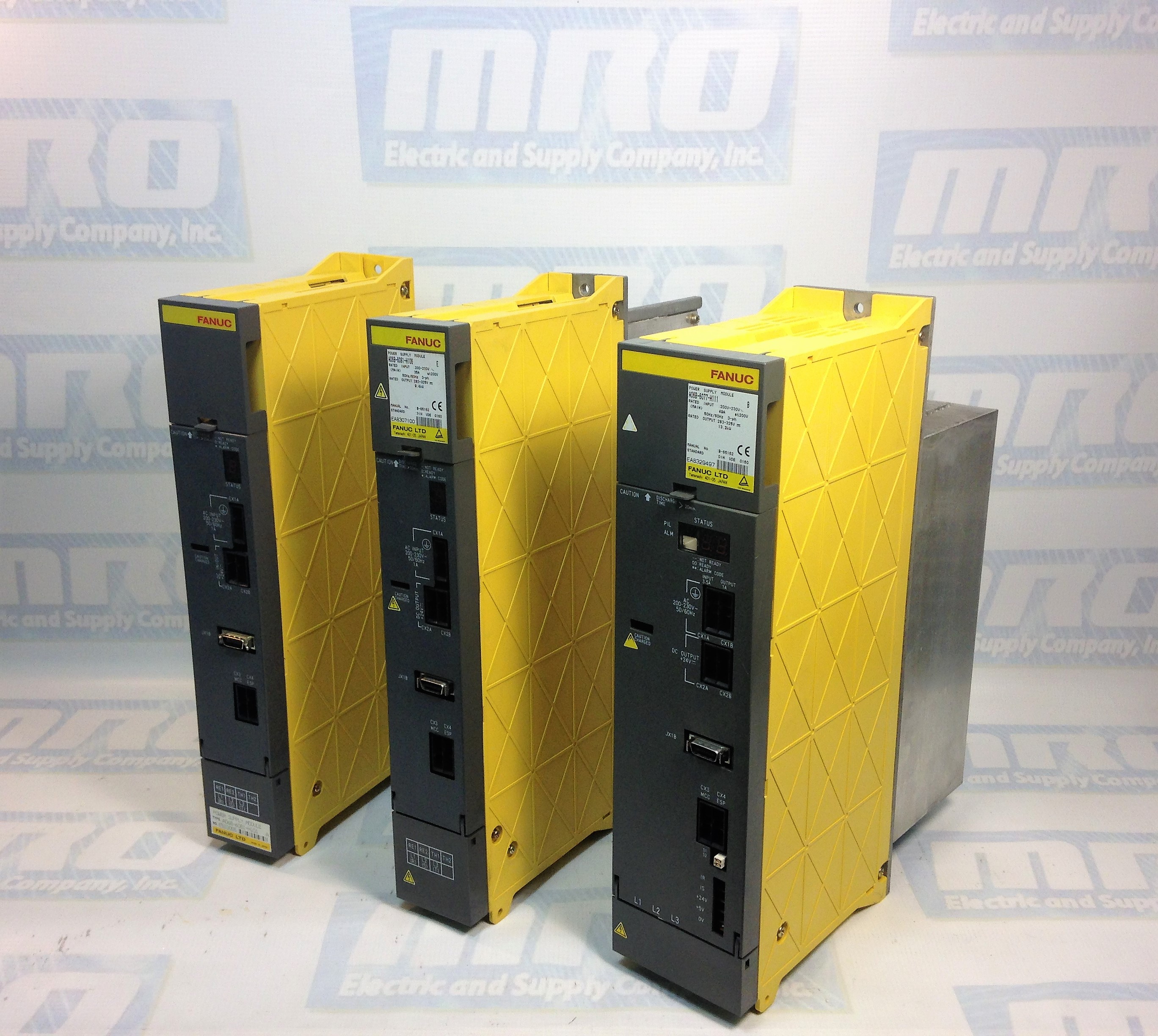
Use the list below to interpret what exactly the fault code is trying to communicate. If you require a replacement part, know that MRO Electric stocks thousands of FANUC CNC replacements. Get your new FANUC servo amplifier or check out our FANUC servo motors. To order a replacement part or a repair job, please call 800-691-8511 or email sales@mroelectric.com. Curious about other common FANUC CNC problems? Check out our FAQ here.
These FANUC Alarms are valid for following FANUC Controls:
• 0i Model A
• 0i/0iMate Model B
• 16/18 Model PB
• 16/18 Model C
• 16i/18i Model A
• 16i/18i Model B
• 16iL Model A
• 20i
• 21 Model B
• 21i Model A
• 21i Model B
• 21i Model A
| Alarm | Description |
| 0 PLEASE TURN OFF POWER | A parameter which requires the power off was input, turn off power. |
| 1 TH PARITY ALARM | TH alarm (A character with incorrect parity was input). Correct the tape. |
| 2 TV PARITY ALARM | TV alarm (The number of characters in a block is odd). This alarm will be generated only when the TV check is effective. |
| 3 TOO MANY DIGITS | Data exceeding the maximum allowable number of digits was input. (Refer to the item of max. programmable dimensions.) |
| 4 ADDRESS NOT FOUND | A numeral or the sign “ – ” was input without an address at the beginning of a block. Modify the program. |
| 5 NO DATA AFTER ADDRESS | The address was not followed by the appropriate data but was followed by another address or EOB code. Modify the program. |
| 6 ILLEGAL USE OF NEGATIVE SIGN | Sign “ – ” input error (Sign “ – ” was input after an address with which it cannot be used. Or two or more “ – ” signs were input.) Modify the program. |
| 7 ILLEGAL USE OF DECIMAL POINT | Decimal point “.” input error (A decimal point was input after an address with which it can not be used. Or two decimal points were input.) Modify the program. |
| 9 ILLEGAL ADDRESS INPUT | Unusable character was input in significant area. Modify the program. |
| 10 IMPROPER G–CODE | An unusable G code or G code corresponding to the function not provided is specified. Modify the program. |
| 11 NO FEEDRATE COMMANDED | Feedrate was not commanded to a cutting feed or the feedrate was inadequate. Modify the program. |
| 14 CAN NOT COMMAND G95 (M Series) | A synchronous feed is specified without the option for threading / synchronous feed. |
| 14 ILLEGAL LEAD COMMAND (T Series) | In variable lead threading, the lead incremental and decremental outputted by address K exceed the maximum command value or a command such that the lead becomes a negative value is given. Modify the program. |
| 15 TOO MANY AXES COMMANDED | M Series;An attempt was made to move the machine along the axes, but the number of the axes exceeded the specified number of axes controlled simultaneously. Modify the program. |
| 20 OVER TOLERANCE OF RADIUS | In circular interpolation (G02 or G03), difference of the distance between the start point and the center of an arc and that between the end point and the center of the arc exceeded the value specified in parameter No. 3410. |
| 21 ILLEGAL PLANE AXIS COMMANDED | An axis not included in the selected plane (by using G17, G18, G19) was commanded in circular interpolation. Modify the program. |
| 22 NO CIRCULAR RADIUS | When circular interpolation is specified, neither R (specifying an arc radius), nor I, J, and K (specifying the distance from a start point to the center) is specified. |
| 23 ILLEGAL RADIUS COMMAND (T series) | In circular interpolation by radius designation, negative value was commanded for address R. Modify the program. |
| 25 CANNOT COMMAND F0 IN G02/G03 | F0 (fast feed) was instructed by F1 –digit column feed in circular interpolation. Modify the program. |
| 27 NO AXES COMMANDED IN G43/G44 | No axis is specified in G43 and G44 blocks for the tool length offset type C. Offset is not canceled but another axis is offset for the tool length offset type C. Modify the program. |
| 28 ILLEGAL PLANE SELECT | In the plane selection command, two or more axes in the same direction are commanded. Modify the program. |
| 29 ILLEGAL OFFSET VALUE | M Series;The offset values specified by H code is too large. Modify the program. |
| 30 ILLEGAL OFFSET NUMBER | M Series;The offset values specified by D/H code for tool length offset, cutter compensation or 3–dimensional cutter compensation is too large. Otherwise, the number specified by P code for the additional workpiece coordinate system is too large. Modify the program. |
| 31 ILLEGAL P COMMAND IN G10 | In setting an offset amount by G10, the offset number following address P was excessive or it was not specified. Modify the program. |
| 32 ILLEGAL OFFSET VALUE IN G10 | In setting an offset amount by G10 or in writing an offset amount by system variables, the offset amount was excessive. |
| 33 NO SOLUTION AT CRC | M Series: A point of intersection cannot be determined for cutter compensation C. Modify the program. T Series: A point of intersection cannot be determined for tool nose radius compensation. Modify the program. |
| 34 NO CIRC ALLOWED IN ST–UP /EXT BLK | M Series;The start up or cancel was going to be performed in the G02 or G03 mode in cutter compensation C. Modify the program. |
| 35 CAN NOT COMMANDED G39 (M Series) | G39 is commanded in cutter compensation B cancel mode or on the plane other than offset plane. Modify the program. |
| 35 CAN NOT COMMANDED G31 | T series;Skip cutting (G31) was specified in tool nose radius compensation mode. Modify the program. |
| 36 CAN NOT COMMANDED G31 | Skip cutting (G31) was specified in cutter compensation mode.Modify the program. |
| 37 CAN NOT CHANGE PLANE IN CRC | M seires;G40 is commanded on the plane other than offset plane in cutter compensation B. The plane selected by using G17, G18 or G19 is changed in cutter compensation C mode. Modify the program. |
| 38 INTERFERENCE IN CIRCULAR BLOCK | Overcutting will occur in tool radius/tool nose radius/cutter compensation because the arc start point or end point coincides with the arc center. Modify the program. |
| 39 CHF/CNR NOT ALLOWED IN NRC | Chamfering or corner R was specified with a start–up, a cancel, or switching between G41 and G42 in tool nose radius compensation. The program may cause overcutting to occur in chamfering or corner R. Modify the program. |
| 40 INTERFERENCE IN G90/G94 BLOCK | Overcutting will occur in tool nose radius compensation in canned cycle G90 or G94. Modify the program. |
| 41 INTERFERENCE IN CRC | M seires;Overcutting will occur in cutter compensation C. Two or more blocks are consecutively specified in which functions such as the auxiliary function and dwell functions are performed without movement in the cutter compensation mode. Modify the program. |
| 42 G45/G48 NOT ALLOWED IN CRC | Tool offset (G45 to G48) is commanded in cutter compensation. Modify the program. |
| 44 G27–G30 NOT ALLOWED IN FIXED CYC | One of G27 to G30 is commanded in canned cycle mode.Modify the program. |
| 45 ADDRESS Q NOT FOUND(G73/G83) | In canned cycle G73/G83, the depth of each cut (Q) is not specified. Alternatively,Q0 is specified. Correct the program. |
| 46 ILLEGAL REFERENCE RETURN COMMAND | Other than P2, P3 and P4 are commanded for 2nd, 3rd and 4th reference position return command. |
| 47 ILLEGAL AXIS SELECT | Two or more parallel axes (in parallel with a basic axis) have been specified upon start–up of three–dimensional tool compensation or three–dimensional coordinate conversion. |
| 48 BASIC 3 AXIS NOT FOUND | For startup of three–dimensional tool compensation or three–dimensional coordinate conversion, the three basic axes used when Xp,Yp and Zp are omitted were not specified in parameter No. 1022. |
| 49 ILLEGAL OPERATION (G68/G69) | The commands for three–dimensional coordinate conversion (G68,G69) and tool length compensation (G43, G44, G45) are not nested.Modify the program. |
| 50 CHF/CNR NOT ALLOWED IN THRD BLK | Chamfering or corner R is commanded in the thread cutting block. Modify the program. |
| 51 MISSING MOVE AFTER CHF/CNR | T series;Improper movement or the move distance was specified in the block next to the chamfering or corner R block.Modify the program. |
| 52 CODE IS NOT G01 AFTER CHF/CNR | The block next to the chamfering or corner R block is not G01, G02,or G03.Modify the program. |
| 53 TOO MANY ADDRESS COMMANDS | M series;For systems without the arbitary angle chamfering or corner R cutting, a comma was specified. For systems with this feature, a comma was followed by something other than R or C Correct the program. |
| 54 NO TAPER ALLOWED AFTER CHF/CNR | T series;A block in which chamfering in the specified angle or the corner R was specified includes a taper command. Modify the program. |
| 55 MISSING MOVE VALUE IN CHF/CNR | In chamfering or corner R block, the move distance is less than chamfer or corner R amount. Modify the program. |
| 56 NO END POINT & ANGLE IN CHF/CNR | T series;Neither the end point nor angle is specified in the command for the block next to that for which only the angle is specified (A). In the chamfering comman, I(K) is commanded for the X(Z) axis. |
| 57 NO SOLUTION OF BLOCK END | Block end point is not calculated correctly in direct dimension drawing programming. Modify the program. |
| 58 END POINT NOT FOUND | In a arbitrary angle chamfering or corner R cutting block, a specified axis is not in the selected plane. Correct the program. |
| 59 PROGRAM NUMBER NOT FOUND | In an external program number search, a specified program number was not found. Otherwise, a program specified for searching is being edited in background processing. Alternatively, the program with the program number specified in a one–touch macro call is not found in memory. Check the program number and external signal. Or discontinue the background editing. |
| 60 SEQUENCE NUMBER NOT FOUND | Commanded sequence number was not found in the sequence number search.Check the sequence number. |
| 61 ADDRESS P/Q NOT FOUND IN G70–G73 | T series;Address P or Q is not specified in G70, G71, G72, or G73 command. Modify the program. |
| 62 ILLEGAL COMMAND IN G71–G76 | T series;1. The depth of cut in G71 or G72 is zero or negative value.;2. The repetitive count in G73 is zero or negative value.;3. the negative value is specified to Δi or Δk is zero in G74 or G75.;4. A value other than zero is specified to address U or W though Δi or Δk is zero in G74 or G75.;5. A negative value is specified to Δd, though the relief direction in G74 or G75 is determined.;6. Zero or a negative value is specified to the height of thread or depth of cut of first time in G76.;7. The specified minimum depth of cut in G76 is greater than the height of thread.;8. An unusable angle of tool tip is specified in G76.;Modify the program. |
| 63 SEQUENCE NUMBER NOT FOUND | T series;The sequence number specified by address P in G70, G71, G72, or G73 command cannot be searched. Modify the program. |
| 64 SHAPE PROGRAM NOT MONOTONOUSLY | T series;A target shape which cannot be made by monotonic machining was specified in a repetitive canned cycle (G71 or G72). |
| 65 ILLEGAL COMMAND IN G71–G73 | T series;1. G00 or G01 is not commanded at the block with the sequence number which is specified by address P in G71, G72, or G73 command.;2. Address Z(W) or X(U) was commanded in the block with a sequence number which is specified by address P in G71 or G72, respectively. Modify the program. |
| 66 IMPROPER G–CODE IN G71–G73 | T series;An unallowable G code was commanded beween two blocks specified by address P in G71, G72, or G73. Modify the program. |
| 67 CAN NOT ERROR IN MDI MODE | T series;G70, G71, G72, or G73 command with address P and Q. Modify the program. |
| 69 FORMAT ERROR IN G70–G73 | T series;The final move command in the blocks specified by P and Q of G70, G71, G72, and G73 ended with chamfering or corner R. Modify the program. |
| 70 NO PROGRAM SPACE IN MEMORY | The memory area is insufficient.Delete any unnecessary programs, then retry. |
| 71 DATA NOT FOUND | The address to be searched was not found.Or the program with specified program number was not found in program number search.Check the data. |
| 72 TOO MANY PROGRAMS | The number of programs to be stored exceeded 63 (basic), 125 (option),200 (option), or 400 (option) or 1000 (option). Delete unnecessary programs and execute program registeration again. |
| 73 PROGRAM NUMBER ALREADY IN USE | The commanded program number has already been used. Change the program number or delete unnecessary programs and execute program registeration again. |
| 74 ILLEGAL PROGRAM NUMBER | The program number is other than 1 to 9999.Modify the program number. |
| 75 PROTECT | An attempt was made to register a program whose number was protected. |
| 76 ADDRESS P NOT DEFINED | Address P (program number) was not commanded in the block which includes an M98, G65, or G66 command. Modify the program. |
| 77 SUB PROGRAM NESTING ERROR | The subprogram was called in five folds. Modify the program. |
| 78 NUMBER NOT FOUND | A program number or a sequence number which was specified by address P in the block which includes an M98, M99, M65 or G66 was not found.The sequence number specified by a GOTO statement was not found. Otherwise, a called program is being edited in background processing.Correct the program, or discontinue the background editing. |
| 79 PROGRAM VERIFY ERROR | In memory or program collation,a program in memory does not agree with that read from an external I/O device. Check both the programs in memory and those from the external device. |
| 80 G37 ARRIVAL SIGNAL NOT ASSERTED | M series;In the automatic tool length measurement function (G37), the measurement position reach signal (XAE, YAE,or ZAE) is not turned on within an area specified in parameter 6254 (value ε).This is due to a setting or operator error. |
| 81 OFFSET NUMBER NOT FOUND IN G37 | M series;Tool length automatic measurement (G37) was specified without a H code.(Automatic tool length measurement function) Modify the program. |
| 82 H–CODE NOT ALLOWED IN G37 | M series;H code and automatic tool compensation (G37) were specified in the same block. (Automatic tool length measurement function) Modify the program. |
| 82 T–CODE NOT ALLOWED IN G37 | T series;T code and automatic tool compensation (G36, G37) were specified in the same block. (Automatic tool compensation function) Modify the program. |
| 83 ILLEGAL AXIS COMMAND IN G37 | M series;In automatic tool length measurement, an invalid axis was specified or the command is incremental.Modify the program. |
| 85 COMMUNICATION ERROR | When entering data in the memory by using Reader / Puncher interface,an overrun, parity or framing error was generated. The number of bits of input data or setting of baud rate or specification No. of I/O unit is incorrect. |
| 86 DR SIGNAL OFF | When entering data in the memory by using Reader / Puncher interface,the ready signal (DR) of reader / puncher was off.Power supply of I/O unit is off or cable is not connected or a P.C.B. is defective. |
| 87 BUFFER OVERFLOW | When entering data in the memory by using Reader / Puncher interface,though the read terminate command is specified, input is not interrupted after 10 characters read. I/O unit or P.C.B. is defective. |
| 88 LAN FILE TRANS ERROR (CHANNEL–1) | File data transfer over the OSI–Ethernet was terminated as a result of a transfer error. |
| 89 LAN FILE TRANS ERROR (CHANNEL–2) | File data transfer over the OSI–Ethernet was terminated as a result of a transfer error. |
| 90 REFERENCE RETURN INCOMPLETE | 21 Model B;The reference position return cannot be performed normally because the reference position return start point is too close to the reference position or the speed is too slow. Separate the start point far enough from the reference position, or specify a sufficiently fast speed for reference position return. Check the program contents. |
| 91 REFERENCE RETURN INCOMPLETE | In the automatic operation halt state, manual reference position return cannot be performed. |
| 92 AXES NOT ON THE REFERENCE POINT | The commanded axis by G27 (Reference position return check) did not return to the reference position. |
| 94 P TYPE NOT ALLOWED (COORD CHG) | P type cannot be specified when the program is restarted. (After the automatic operation was interrupted, the coordinate system setting operation was performed.) Perform the correct operation according to the operator’s manual. |
| 95 P TYPE NOT ALLOWED (EXT OFS CHG) | P type cannot be specified when the program is restarted.(After the automatic operation was interrupted, the external workpiece offset amount changed.) Perform the correct operation according to the User’s manual. |
| 96 P TYPE NOT ALLOWED (WRK OFS CHG) | P type cannot be specified when the program is restarted.(After the automatic operation was interrupted, the workpiece offset amount changed.) Perform the correct operation according to the User’s manual. |
| 97 P TYPE NOT ALLOWED (AUTO EXEC) | P type cannot be directed when the program is restarted.(After power ON, after emergency stop or P/S alarm 94 to 97 were reset, no automatic operation is performed).Perform automatic operation. |
| 98 G28 FOUND IN SEQUENCE RETURN | A command of the program restart was specified without the reference position return operation after power ON or emergency stop, and G28 was found during search. Perform the reference position return. |
| 99 MDI EXEC NOT ALLOWED AFT.SEARCH | After completion of search in program restart, a move command is given with MDI. Move axis before a move command or don’t interrupt MDI operation. |
| 100 PARAMETER WRITE ENABLE | On the PARAMETER(SETTING) screen, PWE(parameter writing enabled) is set to 1. Set it to 0, then reset the system. |
| 101 PLEASE CLEAR MEMORY | The power turned off while rewriting the memory by program edit operation.If this alarm has occurred, press (RESET) while pressing (PROG),and only the program being edited will be deleted.Register the deleted program. |
| 109 FORMAT ERROR IN G08 | A value other than 0 or 1 was specified after P in the G08 code, or no value was specified. |
| 110 DATA OVERFLOW | The absolute value of fixed decimal point display data exceeds the allowable range. Modify the program. |
| 111 CALCULATED DATA OVERFLOW | The result of calculation turns out to be invalid, an alarm No.111 is issued. –10 47 to –10 –29, 0, 10 –29 to 10 47 Modify the program. |
| 112 DIVIDED BY ZERO | Division by zero was specified.(including tan 90°) Modify the program. |
| 113 IMPROPER COMMAND | A function which cannot be used in custom macro is commanded. Modify the program. |
| 114 FORMAT ERROR IN MACRO | There is an error in other formats than (Formula). Modify the program. |
| 115 ILLEGAL VARIABLE NUMBER | A value not defined as a variable number is designated in the custom macro. Modify the program. |
| 116 WRITE PROTECTED VARIABLE | The left side of substitution statement is a variable whose substitution is inhibited. Modify the program. |
| 118 PARENTHESIS NESTING ERROR | The nesting of bracket exceeds the upper limit (quintuple). Modify the program. |
| 119 ILLEGAL ARGUMENT | The SQRT argument is negative, BCD argument is negative, or other values than 0 to 9 are present on each line of BIN argument. Modify the program. |
| 122 FOUR FOLD MACRO MODAL–CALL | The macro modal call is specified four fold. Modify the program. |
| 123 CAN NOT USE MACRO COMMAND IN DNC | Macro control command is used during DNC operation. Modify the program. |
| 124 MISSING END STATEMENT | DO – END does not correspond to 1: 1. Modify the program. |
| 125 FORMAT ERROR IN MACRO | (Formula) format is erroneous. Modify the program. |
| 126 ILLEGAL LOOP NUMBER | In DOn, 1 = n = 3 is not established. Modify the program. |
| 127 NC, MACRO STATEMENT IN SAME BLOCK | NC and custom macro commands coexist. Modify the program. |
| 128 ILLEGAL MACRO SEQUENCE NUMBER | The sequence number specified in the branch command was not 0 to 9999. Or, it cannot be searched.Modify the program. |
| 129 ILLEGAL ARGUMENT ADDRESS | An address which is not allowed in (Argument Designation) is used.Modify the program. |
| 130 ILLEGAL AXIS OPERATION | An axis control command was given by PMC to an axis controlled by CNC.Or an axis control command was given by CNC to an axis controlled by PMC. Modify the program. |
| 131 TOO MANY EXTERNAL ALARM MESSAGES | Five or more alarms have generated in external alarm message.Consult the PMC ladder diagram to find the cause. |
| 132 ALARM NUMBER NOT FOUND | No alarm No.concerned exists in external alarm message clear.Check the PMC ladder diagram. |
| 133 ILLEGAL DATA IN EXT. ALARM MSG | Small section data is erroneous in external alarm message or external operator message. Check the PMC ladder diagram. |
| 135 ILLEGAL ANGLE COMMAND | M series;The index table indexing positioning angle was instructed in other than an integral multiple of the value of the minimum angle. Modify the program. |
| 135 SPINDLE ORIENTATION PLEASE | T series;Without any spindle orientation, an attept was made for spindle indexing. Perform spindle orientation. |
| 136 ILLEGAL AXIS COMMAND | M series;In index table indexing.Another control axis was instructed together with the B axis. Modify the program. |
| 136 C/H–CODE & MOVE CMD IN SAME BLK. | T series;A move command of other axes was specified to the same block as spindle indexing addresses C, H. Modify the program. |
| 137 M–CODE & MOVE CMD IN SAME BLK. | A move command of other axes was specified to the same block as M–code related to spindle indexing. Modify the program. |
| 138 SUPERIMPOSED DATA OVERFLOW | The total distribution amount of the CNC and PMC is too large during superimposed control of the extended functions for PMC axis control. |
| 139 CAN NOT CHANGE PMC CONTROL AXIS | An axis is selected in commanding by PMC axis control. Modify the program. |
| 141 CAN NOT COMMAND G51 IN CRC | M series;G51 (Scaling ON) is commanded in the tool offset mode. Modify the program. |
| 142 ILLEGAL SCALE RATE | M series;Scaling magnification is commanded in other than 1 to 999999. Correct the scaling magnification setting (G51 Pp………………… or parameter 5411 or 5421). |
| 143 SCALED MOTION DATA OVERFLOW | M series;The scaling results, move distance, coordinate value and circular radius exceed the maximum command value. Correct the program or scaling mangification. |
| 144 ILLEGAL PLANE SELECTED | M series;The coordinate rotation plane and arc or cutter compensation C plane must be the same. Modify the program. |
| 145 ILLEGAL CONDITIONS IN POLAR COORDINATE INTERPOLATION | The conditions are incorrect when the polar coordinate interpolation starts or it is canceled.;1) In modes other than G40, G12.1/G13.1 was specified.;2) An error is found in the plane selection. Parameters No. 5460 and No. 5461 are incorrectly specified.;Modify the value of program or parameter. |
| 146 IMPROPER G CODE | G codes which cannot be specified in the polar coordinate interpolation mode was specified. See section II to 4.4 and modify the program. |
| 148 ILLEGAL SETTING DATA | M series;Automatic corner override deceleration rate is out of the settable range of judgement angle. Modify the parameters (No.1710 to No.1714) |
| 149 FORMAT ERROR IN G10L3 | M series;A code other than Q1,Q2,P1 or P2 was specified as the life count type in the extended tool life management. |
| 150 ILLEGAL TOOL GROUP NUMBER | Tool Group No. exceeds the maximum allowable value. Modify the program. |
| 151 TOOL GROUP NUMBER NOT FOUND | The tool group commanded in the machining program is not set. Modify the value of program or parameter. |
| 152 NO SPACE FOR TOOL ENTRY | The number of tools within one group exceeds the maximum value registerable. Modify the number of tools. |
| 153 T–CODE NOT FOUND | In tool life data registration, a T code was not specified where one should be. Correct the program. |
| 154 NOT USING TOOL IN LIFE GROUP | M series;When the group is not commanded, H99 or D99 was commanded. Correct the program. |
| 155 ILLEGAL T–CODE IN M06 | M series;In the machining program, M06 and T code in the same block do not correspond to the group in use. Correct the program. |
| 156 P/L COMMAND NOT FOUND | P and L commands are missing at the head of program in which the tool group is set. Correct the program. |
| 157 TOO MANY TOOL GROUPS | The number of tool groups to be set exceeds the maximum allowable value. (See parameter No. 6800 bit 0 and 1) Modify the program. |
| 158 ILLEGAL TOOL LIFE DATA | The tool life to be set is too excessive. Modify the setting value. |
| 159 TOOL DATA SETTING INCOMPLETE | During executing a life data setting program, power was turned off. Set again. |
| 163 COMMAND G68/G69 INDEPENDENTLY | G68 and G69 are not independently commanded in balance cut. Modify the program. |
| 175 ILLEGAL G107 COMMAND | Conditions when performing circular interpolation start or cancel not correct. To change the mode to the cylindrical interpolation mode, specify the command in a format of “G07.1 rotation to axis name radius of cylinder.” |
| 176 IMPROPER G–CODE IN G107 | M series;Any of the following G codes which cannot be specified in the cylindrical interpolation mode was specified.;1) G codes for positioning: G28,, G73, G74, G76, G81 – G89, including the codes specifying the rapid traverse cycle;2) G codes for setting a coordinate system: G52,G92;3) G code for selecting coordinate system: G53 G54–G59 Modify the program. |
| 177 CHECK SUM ERROR (G05 MODE) | Check sum error Modify the program. |
| 178 G05 COMMANDED IN G41/G42 MODE | G05 was commanded in the G41/G42 mode. Correct the program. |
| 179 PARAM. (NO. 7510) SETTING ERROR | The number of controlled axes set by the parameter 7510 exceeds the maximum number. Modify the parameter setting value. |
| 180 COMMUNICATION ERROR (REMOTE BUF) | Remote buffer connection alarm has generated. Confirm the number of cables, parameters and I/O device. |
| 181 FORMAT ERROR IN G81 BLOCK | G81 block format error (hobbing machine);1) T (number of teeth) has not been instructed.;2) Data outside the command range was instructed by either T, L, Q or P.;3) An overflow occurred in synchronization coefficient calculation. Modify the program. |
| 182 G81 NOT COMMANDED | G83 (C axis servo lag quantity offset) was instructed though synchronization by G81 has not been instructed. Correct the program. (hobbing machine) |
| 183 DUPLICATE G83 (COMMANDS) | G83 was instructed before canceled by G82 after compensating for the C axis servo lag quantity by G83. (hobbing machine) |
| 184 ILLEGAL COMMAND IN G81 | A command not to be instructed during synchronization by G81 was instructed. (hobbing machine);1) A C axis command by G00, G27, G28, G29, G30, etc. was instructed.;2) Inch/Metric switching by G20, G21 was instructed. |
| 185 RETURN TO REFERENCE POINT | G81 was instructed without performing reference position return after power on or emergency stop. (hobbing machine) Perform reference position return. |
| 186 PARAMETER SETTING ERROR | Parameter error regarding G81 (hobbing machine);1) The C axis has not been set to be a rotary axis.;2) A hob axis and position coder gear ratio setting error Modify the parameter. |
| 187 HOB COMMAND IS NOT ALLOWED | Error in the modal state when G81.4 or G81 is specified;1. The canned cycle mode (G81 to G89) is set.;2. The thread cutting mode is set.;3. The C–axis is under synchronous, composite, or superimposed control. |
| 190 ILLEGAL AXIS SELECT | M series;In the constant surface speed control, the axis specification is wrong. (See parameter No. 3770.) The specified axis command (P) contains an illegal value. Correct the program. |
| 194 SPINDLE COMMAND IN SYNCHRO–MODE | A contour control mode, spindle positioning (Cs–axis control) mode, or rigid tapping mode was specified during the serial spindle synchronous control mode. Correct the program so that the serial spindle synchronous control mode is released in advance. |
| 195 MODE CHANGE ERROR | Switching command to contouring mode, Cs axis control or rigid tap mode or switching to spindle command mode is not correctly completed. (This occurs when the response to switch to the spindle control unit side with regard to the switching command from the NC is incorrect. This alarm is not for the purposes of warning against mistakes in operation, but because continuing operation in this condition can be dangerous it is a P/S alarm.) |
| 197 C–AXIS COMMANDED IN SPINDLE MODE | The program specified a movement along the Cs–axis when the signal CON(DGN=G027#7) was off. Correct the program, or consult the PMC ladder diagram to find the reason the signal is not turned on. |
| 199 MACRO WORD UNDEFINED | Undefined macro word was used. Modify the custom macro. |
| 200 ILLEGAL S CODE COMMAND | In the rigid tap, an S value is out of the range or is not specified. Modify the program. |
| 201 FEEDRATE NOT FOUND IN RIGID TAP | In the rigid tap, no F value is specified. Correct the program. |
| 202 POSITION LSI OVERFLOW | In the rigid tap, spindle distribution value is too large. (System error) |
| 203 PROGRAM MISS AT RIGID TAPPING | In the rigid tap, position for a rigid M code (M29) or an S command is incorrect. Modify the program. |
| 204 ILLEGAL AXIS OPERATION | In the rigid tap, an axis movement is specified between the rigid M code (M29) block and G84 or G74 for M series (G84 or G88 for T series) block. Modify the program. |
| 205 RIGID MODE DI SIGNAL OFF | Rigid mode DI signal is not ON when G84 or G74 for M series (G84 or G88 for T series) is executed though the rigid M code (M29) is specified. Consult the PMC ladder diagram to find the reason the DI signal (DGNG061.1) is not turned on. |
| 206 CAN NOT CHANGE PLANE (RIGID TAP) | M series;Plane changeover was instructed in the rigid mode. Correct the program. |
| 207 RIGID DATA MISMATCH | The specified distance was too short or too long in rigid tapping. |
| 210 CAN NOT COMAND M198/M199 | M198 and M199 are executed in the schedule operation. M198 is executed in the DNC operation. Modify the program.;1) The execution of an M198 or M99 command was attempted during scheduled operation. Alternatively, the execution of an M198 command was attempted during DNC operation. Correct the program.;2) The execution of an M99 command was attempted by an interrupt macro during pocket machining in a multiple repetitive canned cycle. |
| 211 G31 (HIGH) NOT ALLOWED IN G99 | G31 is commanded in the per revolution command when the high– speed skip option is provided. Modify the program. |
| 212 ILLEGAL PLANE SELECT | M series;The arbitrary angle chamfering or a corner R is commanded or the plane including an additional axis. Correct the program. |
| 213 ILLEGAL COMMAND IN SYNCHRO–MODE | Movement is commanded for the axis to be synchronously controlled. Any of the following alarms occurred in the operation with the simple synchronization control.;1) The program issued the move command to the slave axis.;2) The program issued the manual continuous feed/manual handle feed/incremental feed command to the slave axis.;3) The program issued the automatic reference position return command without specifying the manual reference position return after the power was turned on.;4) The difference between the position error amount of the master and slave axes exceeded the value specified in parameter NO.8313. |
| 214 ILLEGAL COMMAND IN SYNCHRO–MODE | Coordinate system is set or tool compensation of the shift type is executed in the synchronous control. Correct the program. |
| 217 DUPLICATE G51.2 (COMMANDS) | T series;G51.2/G251 is further commanded in the G51.2/G251 mode. Modify the program. |
| 218 NOT FOUND P/Q COMMAND IN G251 (T series) | T series;P or Q is not commanded in the G251 block, or the command value is out of the range. Modify the program. |
| 219 COMMAND G250/G251 INDEPENDENTLY | T series;G251 and G250 are not independent blocks. |
| 220 ILLEGAL COMMAND IN SYNCHR–MODE | T series;In the synchronous operation, movement is commanded by the NC program or PMC axis control interface for the synchronous axis. |
| 221 ILLEGAL COMMAND IN SYNCHR–MODE | T series;Polygon machining synchronous operation and axis control or balance cutting are executed at a time. Modify the program. |
| 222 DNC OP. NOT ALLOWED IN BG.–EDIT | M series;Input and output are executed at a time in the background edition. Execute a correct operation. |
| 224 RETURN TO REFERENCE POINT | M series;Reference position return has not been performed before the automatic operation starts. Perform reference position return only when bit 0 of parameter 1005 is 0. |
| 225 SYNCHRONOUS/MIXED CONTROL ERROR | T series (At two–path);This alarm is generated in the following circumstances. (Searched for during synchronous and mixed control command.;1 When there is a mistake in axis number parameter (No. 1023) setting.;2 When there is a mistake in control commanded. During hobbing synchronization, a command to bring the C–axis under synchronous, composite, or superimposed control is made. Modify the program or the parameter. |
| 226 ILLEGAL COMMAND IN SYNCHRO– MODE | T series (At two–path);A travel command has been sent to the axis being synchronized in synchronous mode. Modify the program or the parameter. |
| 229 CAN NOT KEEP SYNCHRO–STATE | T series;This alarm is generated in the following circumstances.;1 When the synchro/mixed state could not be kept due to system overload.;2 The above condition occurred in CMC devices (hardware) and synchro– state could not be kept.;(This alarm is not generated in normal use conditions.) |
| 230 R CODE NOT FOUND | The infeed quantity R has not been instructed for the G161 block. Or the R command value is negative. Correct the program. |
| 231 ILLEGAL FORMAT IN G10 OR L50 | Any of the following errors occurred in the specified format at the programmable– parameter input.;1 Address N or R was not entered.;2 A number not specified for a parameter was entered.;3 The axis number was too large.;4 An axis number was not specified in the axis–type parameter.;5 An axis number was specified in the parameter which is not an axis type. Correct the program.;6 An attempt was made to reset bit 4 of parameter 3202 (NE9) or change parameter 3210 (PSSWD) when they are protected by a password.;Correct the program. |
| 233 DEVICE BUSY | When an attempt was made to use a unit such as that connected via the RS–232–C interface, other users were using it. |
| 239 BP/S ALARM | While punching was being performed with the function for controlling external I/O units,background editing was performed. |
| 240 BP/S ALARM | Background editing was performed during MDI operation |
| 244 P/S ALARM | T series;In the skip function activated by the torque limit signal, the number of accumulated erroneous pulses exceed 32767 before the signal was input. Therefore, the pulses cannot be corrected with one distribution. Change the conditions, such as feed rates along axes and torque limit, and try again. |
| 245 T–CODE NOT ALOWEE IN THIS BLOCK | T series;One of the G codes, G50, G10, and G04, which cannot be specified in the same block as a T code, was specified with a T code. |
| 251 ATC ERROR | This alarm is issued in the following cases;– An M06T_ command contains an unusable T code.;– An M06 command has been specified when the Z machine coordi nate is positive.;– The parameter for the current tool number (No. 7810) is set to 0.;– An M06 command has been specified in canned cycle mode.;– A reference position return command (G27 to G44) and M06 command have been specified in the same block.;– An M06 command has been specified in tool compensation mode (G41 to G44).;– An M06 command has been specified without performing reference position return after power–on or the release of emergency stop.;– The machine lock signal or Z–axis ignore signal has been turned on during tool exchange.;– A pry alarm has been detected during tool exchange. Refer to diagnosis No. 530 to determine the cause. (Only for ROBODRILL) |
| 252 ATC SPINDLE ALARM | An excessive error arose during spindle positioning for ATC. For details, refer to diagnosis No. 531. (Only for ROBODRILL) |
| 253 G05 IS NOT AVAILABLE | M series;Alarm details Binary input operation using high–speed remote buffer (G05) or high– speed cycle machining (G05) has been specified in advance control mode (G08P1). Execute G08P0, to cancel advance control mode, before executing these G05 commands. |
| 4500 REPOSITIONING INHIBITED | A repositioning command was specified in the circular interpolation (G02, G03) mode. |
| 4502 ILLEGAL COMMAND IN BOLT HOLE | In a bolt hole circle (G26) command, the radius (I) was set to zero or a negative value, or the number of holes (K) was set to zero. Alternatively, I, J, or K was not specified. |
| 4503 ILLEGAL COMMAND IN LINE AT ANGLE | In a line-at-angle (G76) command, the number of holes (K) was set to zero or a negative value. Alternatively, I, J, or K was not specified. |
| 4504 ILLEGAL COMMAND IN ARC | In an arc (G77) command, the radius (I) or the number of holes (K) was set to zero or a negative value. Alternatively, I, J, K, or P was not specified. |
| 4505 ILLEGAL COMMAND IN GRID | In a grid (G78, G79) command, the number of holes (P, K) was set to zero or a negative value. Alternatively, I, J, K, or P was not specified. |
| 4506 ILLEGAL COMMAND IN SHARE PROOFS | In a shear proof (G86) command, the tool size (P) was set to zero, or the blanking length (I) was 1.5 times larger than the tool size (P) or less. Alternatively, I, J, or P was not specified. |
| 4507 ILLEGAL COMMAND IN SQUARE | In a square (G87) command, the tool size (P,Q) was set to zero or a negative value, or the blanking length (I, J) was three times larger than the tool size (P, Q) or less. Alternatively, I, J, P, or Q was not specified. |
| 4508 ILLEGAL COMMAND IN RADIUS | In a radius (G88) command, the traveling pitch (Q) or radius (I) was set to zero or a negative value, or the traveling pitch (Q) was greater than or equal to the arc length. Alternatively, I, J, K, P, or Q was not specified. |
| 4509 ILLEGAL COMMAND IN CUT AT ANGLE | In a cut-at-angle (G89) command, the traveling pitch (Q) was set to zero, negative value, or another value larger than or equal to the length (I). Alternatively, I, J, P, or Q was not specified. |
| 4510 ILLEGAL COMMAND IN LINE-PUNCH | In a linear punching (G45) command, the traveling distance was set to zero or a value 1.5 times larger than the tool size (P) or less. Alternatively, P was not specified. |
| 4511 ILLEGAL COMMAND IN CIRCLE-PUNCH | In a circular punching (G46, G47) command, the same position was specified for both start and end points of the arc, radius (R) of the arc was set to zero, or the pitch (Q) was set to a value exceeding the arc length. Alternatively, R or Q was not specified. |
| 4520 T, M INHIBITED IN NIBBLING-MODE | T code, M code, G04, G70 or G75 was specified in the nibbling mode. |
| 4521 EXCESS NIBBLING MOVEMENT (X, Y) | In the nibbling mode, the X-axis or Y-axis traveling distance was larger than or equal to the limit (No. 16188 to 16193). |
| 4522 EXCESS NIBBLING MOVEMENT (C) | In the circular nibbling (G68) or usual nibbling mode, the C-axis traveling distance was larger than or equal to the limit (No. 16194). |
| 4523 ILLEGAL COMMAND IN CIRCLE-NIBBL | In a circular nibbling (G68) command, the traveling pitch (Q) was set to zero, a negative value, or a value larger than or equal to the limit (No. 16186, 16187), or the radius (I) was set to zero or a negative value. Alternatively, I, J, K, P, or Q was not specified. |
| 4524 ILLEGAL COMMAND IN LINE-NIBBL | In a linear nibbling (G69) command, the traveling pitch (Q) was set to zero, negative value, or a value larger than or equal to the limit (No. 16186, 16187). Alternatively, I, J, P, or Q was not specified. |
| 4530 A/B MACRO NUMBER ERROR | The number for storing and calling by an A or B macro was set to a value beyond the range from 1 to 5. |
| 4531 U/V MACRO FORMAT ERROR | An attempt was made to store a macro while storing another macro using a U or V macro. A V macro was specified although the processing to store a macro was not in progress. A U macro number and V macro number do not correspond with each other. |
| 4532 IMPROPER U/V MACRO NUMBER | The number of an inhibited macro (number beyond the range from 01 to 99) was specified in a U or V macro command. |
| 4533 U/V MACRO MEMORY OVERFLOW | An attempt was made to store too many macros with a U or V macro command. |
| 4534 W MACRO NUMBER NOT FOUND | Macro number W specified in a U or V macro command is not stored. |
| 4535 U/V MACRO NESTING ERROR | An attempt was made to call a macro which is defined three times or more using a U or V macro command. An attempt was made to store 15 or more macros in the storage area for macros of number 90 to 99. |
| 4536 NO W, Q COMMAND IN MULTI-PIECE | W or Q was not specified in the command for taking multiple workpieces (G73, G74). |
| 4537 ILLEGAL Q VALUE IN MULTI-PIECE | In the command for taking multiple workpieces (G73, G74), Q is set to a value beyond the range from 1 to 4. |
| 4538 W NO. NOT FOUND IN MULTI-PIECE | Macro number W specified in the command for taking multiple workpieces (G73, G74) is not stored. |
| 4539 MULTI-PIECE SETTING IS ZERO | The command for taking multiple workpieces (G73, G74) was specified although zero is specified for the function to take multiple workpieces (No. 16206 or signals MLP1 and MLP2 (PMC address G231, #0 and #1)). |
| 4540 MULTI-PIECE COMMAND WITHIN MACRO | The command for taking multiple workpieces (G73, G74) was specified when a U or V macro was being stored. |
| 4542 MULTI-PIECE COMMAND ERROR | Although G98P0 was specified, the G73 command was issued. Although G98K0 was specified, the G74 command was issued. |
| 4543 MULTI-PIECE Q COMMAND ERROR | Although G98P0 was specified, the Q value for the G74 command was not 1 or 3. Although G98K0 was specified, the Q value for the G73 command was not 1 or 2. |
| 4544 MULTI-PIECE RESTART ERROR | In the command for resuming taking multiple workpieces, the resume position (P) is set to a value beyond the range from 1 to total number of workpieces to be machined. |
| 4549 ILLEGAL TOOL DATA FORMAT | The quantity of tool data patterns to be saved is too large to fit the usable area (16 KB). |
| 4600 T, C COMMAND IN INTERPOLATION | In the linear interpolation (G01) mode or circular interpolation (G02, G03) mode, a T command or C-axis command was specified. |
| 4601 INHIBITED T, M COMMAND | In the block of G52, G72, G73, or G74, a T or M command was specified. |
| 4602 ILLEGAL T-CODE | The specified T command is not cataloged on the tool register screen. |
| 4603 C AXIS SYNCHRONOUS ERROR | The difference between the position deviation value of C1 axis and C2 axis exceeds the parameter value (No. 16364, 16365) with the C–axis synchronous control function. |
| 4604 ILLEGAL AXIS OPERATION | A C-axis command was specified in the block containing a T command for multiple tools. |
| 4605 NEED ZRN | C–axis synchronization failed. |
| 4630 ILLEGAL COMMAND IN LASER MODE | In the laser mode, a nibbling command or pattern command was specified. In the tracing mode, an attempt was made to make a switch to the punching mode. |
| 4650 IMPROPER G-CODE IN OFFSET MODE | In the cutter compensation mode, an inhibited G code (pattern command, G73, G74, G75, etc.) was specified. |
| 4700 PROGRAM ERROR (OT +) | The value specified in the X-axis move command exceeded the positive value of stored stroke limit 1. (Advance check) |
| 4701 PROGRAM ERROR (OT –) | The value specified in the X-axis move command exceeded the negative value of stored stroke limit 1. (Advance check) |
| 4702 PROGRAM ERROR (OT +) | The value specified in the Y-axis move command exceeded the positive value of stored stroke limit 1. (Advance check) |
| 4703 PROGRAM ERROR (OT –) | The value specified in the Y-axis move command exceeded the negative value of stored stroke limit 1. (Advance check) |
| 4704 PROGRAM ERROR (OT +) | The value specified in the Z-axis move command exceeded the positive value of stored stroke limit 1. (Advance check) |
| 4705 PROGRAM ERROR (OT –) | The value specified in the Z-axis move command exceeded the negative value of stored stroke limit 1. (Advance check) |
| 5000 ILLEGAL COMMAND CODE | The specified code was incorrect in the high–precision contour control (HPCC) mode. |
| 5003 ILLEGAL PARAMETER | There is an invalid parameter. |
| 5004 HPCC NOT READY | (M series) High–precision contour control is not ready. |
| 5006 TOO MANY WORD IN ONE BLOCK | The number of words specified in a block exceeded 26 in the HPCC mode. |
| 5007 TOO LARGE DISTANCE | In the HPCC mode, the machine moved beyond the limit. |
| 5009 PARAMETER ZERO | The maximum feedrate (parameter No. 1422) or the feedrate in dry run (parameter No. 1410) is 0 in the HPCC model. |
| 5010 END OF RECORD | The end of record (%) was specified. I/O is incorrect. modify the program. |
| 5012 G05 P10000 ILLEGAL START UP | Function category: High–precision contour control;Alarm details: G05 P10000 has been specified in a mode from which the system cannot enter HPCC mode. |
| 5013 HPCC: CRC OFS REMAIN AT CANCEL | G05P0 has been specified in G41/G42 mode or with offset remaining |
| 5014 TRACE DATA NOT FOUND | M series;Transfer cannot be performed because no trace data exists. |
| 5018 POLYGON SPINDLE SPEED ERROR | Function category: Polygon turning;Alarm details: In G51.2 mode, the speed of the spindle or polygon synchronous axis either exceeds the clamp value or is too small. The specified rotation speed ratio thus cannot be maintained. |
| 5020 PARAMETER OF RESTART ERROR | An erroneous parameter was specified for restarting a program. A parameter for program restart is invalid. |
| 5030 ILLEGAL COMMAND (G100) | T series;The end command (G110) was specified before the registratioin start command (G101, G102, or G103) was specified for the B–axis. |
| 5031 ILLEGAL COMMAND (G100, G102, G103) | T series;While a registration start command (G101, G102, or G103) was being executed, another registration start command was specified for the B–axis. |
| 5032 NEW PRG REGISTERED IN B–AXS MOVE | T series;While the machine was moving about the B–axis, at attempt was made to register another move command. |
| 5033 NO PROG SPACE IN MEMORY B–AXS | T series;Commands for movement about the B–axis were not registered because of insufficient program memory |
| 5034 PLURAL COMMAND IN G110 | T series;Multiple movements were specified with the G110 code for the B–axis. |
| 5035 NO FEEDRATE COMMANDED B–AXS | T series;A feedrate was not specified for cutting feed about the B–axis. |
| 5036 ADDRESS R NOT DEFINED IN G81–G86 | T series;Point R was not specified for the canned cycle for the B–axis. |
| 5037 ADDRESS Q NOT DEFINED IN G83 | T series;Depth of cut Q was not specified for the G83 code (peck drilling cycle). Alternatively, 0 was specified in Q for the B–axis. |
| 5038 TOO MANY START M–CODE COMMAND | T series;More than six M codes for starting movement about the B–axis were specified. |
| 5039 START UNREGISTERED B–AXS PROG | T series;An attempt was made to execute a program for the B–axis which had not been registered. |
| 5040 CAN NOT COMMANDED B–AXS MOVE | T series;The machine could not move about the B–axis because parameter No.8250 was incorrectly specified, or because the PMC axis system could not be used. |
| 5041 CAN NOT COMMANDED G110 BLOCK | T series;Blocks containing the G110 codes were successively specified in tool– tip radius compensation for the B–axis. |
| 5044 G68 FORMAT ERROR | M series;A G68 command block contains a format error. This alarm is issued in the following cases;1. I, J, or K is missing from a G68 command block (missing coordinate rotation option).;2. I, J, and K are 0 in a G68 command block.;3. R is missing from a G68 command block. |
| 5046 ILLEGAL PARAMETER (ST.COMP) | The parameter settings for straightness compensation contain an error. Possible causes are as follows;1. A parameter for a movement axis or compensation axis contains an axis number which is not used.;2. More than 128 pitch error compensation points exist between the negative and positive end points.;3. Compensation point numbers for straightness compensation are not assigned in the correct order.;4. No straightness compensation point exists between the pitch error compensation points at the negative and positive ends.;5. The compensation value for each compensation point is too large or too small. |
| 5050 ILL–COMMAND IN CHOPPING MODE | A command for switching the major axis has been specified for circular threading. Alternatively, a command for setting the length of the major axis to 0 has been specified for circular threading. |
| 5051 M–NET CODE ERROR | Abnormal character received (other than code used for transmission) |
| 5052 M–NET ETX ERROR | Abnormal ETX code |
| 5053 M–NET CONNECT ERROR | Connection time monitoring error (parameter No. 175) |
| 5054 M–NET RECEIVE ERROR | Polling time monitoring error (parameter No. 176) |
| 5055 M–NET PRT/FRT ERROR | Vertical parity or framing error |
| 5057 M–NET BOARD SYSTEM DOWN | Transmission timeout error (parameter No. 177) ROM parity error CPU interrupt other than the above |
| 5058 G35/G36 FORMAT ERROR | A command for switching the major axis has been specified for circular threading. Alternatively, a command for setting the length of the major axis to 0 has been specified for circular threading. |
| 5059 RADIUS IS OUT OF RANGE | A radius exceeding nine digits has been specified for circular interpolation with the center of the arc specified with I, J, and K. |
| 5060 ILLEGAL PARAMETER IN G02.3/G03.3 | There is a parameter setting error. Parameter No. 5641 (setting of the linear axis) is not set. The axis set in parameter No. 5641 is not a linear axis. Parameter No. 5642 (setting of a rotation axis) is not set. The axis set in parameter No. 5642 is not a rotation axis. The linear and rotation axes cannot be controlled by the CNC. (The value set in parameter No. 1010 is exceeded.) |
| 5061 ILLEGAL FORMAT IN G02.3/G03.3 | The exponential interpolation command (G02.3/G03.3) has a format error. Address I, J, or K is not specified. The value of address I, J, or K is 0. |
| 5062 ILLEGAL COMMAND IN G02.3/G03.3 | The value specified in an exponential interpolation command (G02.3/03.3) is illegal. A value that does not allow exponential interpolation is specified. (For example, a negative value is specified in In.) |
| 5063 IS NOT PRESET AFTER REF. | Function category: Workpiece thickness measurement Alarm details The position counter was not preset before the start of workpiece thickness measurement. This alarm is issued in the following cases;(1) An attempt has been made to start measurement without first establishing the origin.;(2) An attempt has been made to start measurement without first presetting the position counter after manual return to the origin. |
| 5064 DIFFERRENT AXIS UNIT (IS–B, IS–C) | Circular interpolation has been specified on a plane consisting of axes having different increment systems. |
| 5065 DIFFERENT AXIS UNIT (PMC AXIS) | Axes having different increment systems have been specified in the same DI/DO group for PMC axis control. Modify the setting of parameter No. 8010. |
| 5067 (HPCC) | HPCC mode cannot be canceled during G51 (scaling) or G68 (coordinate system rotation). Correct the program. |
| 5068 G31 FORMAT ERROR | The continuous high–speed skip command (G31 P90) has one of the following errors;1. The axis along which the tool is moved is not specified.;2. More than one axis is specified as the axis along which the tool is moved. |
| 5069 WHL–C:ILLEGA P–DATA | The P data in selection of the grinding–wheel wear compensation center is illegal. |
| 5073 NO DECIMAL POINT | A decimal point is not specified for a command for which a decimal point must be specified. |
| 5074 ADDRESS DUPLICATION ERROR | The same address has been specified two or more times in a single block. Alternatively, two or more G codes in the same group have been specified in a single block. |
| 5082 DATA SERVER ERROR | This alarm is detailed on the data server message screen. |
| 5085 SMOOTH IPL ERROR 1 | A block for specifying smooth interpolation contains a syntax error. |
| 5096 MISMATCH WAITING M–CODE | Different wait codes (M codes) were specified in HEAD1 and HEAD2. Correct the program. |
| 5110 IMPROPER G–CODE | An illegal G code was specified in look–ahead control mode (multi blocks are read in advance). A command was specified for the index table indexing axis in look– ahead control mode (multi blocks are read in advance). |
| 5111 IMPROPER MODAL G–CODE | M series;An illegal G code is left modal when look–ahead control mode was specified. |
| 5112 G08 CAN NOT BE COMMANDED | M series;Look–ahead control (G08) was specified in look–ahead control mode (multi blocks are read in advance). |
| 5113 CAN NOT ERROR IN MDI MODE | Look–ahead control (multi blocks are read in advance) (G05.1) was specified in MDI mode. |
| 5114 NOT STOP POSITION (G05.1 Q1) | At the time of restart after manual intervention, the coordinates at which the manual intervention occurred have not been restored. |
| 5115 SPL: ERROR | There is an error in the specification of the rank. No knot is specified. The knot specification has an error. The number of axes exceeds the limits. Other program errors |
| 5116 SPL: ERROR | There is a program error in a block under look–ahead control. Monotone increasing of knots is not observed. In NURBS interpolation mode, a mode that cannot be used together is specified. |
| 5117 SPL: ERROR | The first control point of NURBS is incorrect. |
| 5118 SPL: ERROR | After manual intervention with manual absolute mode set to on, NURBS interpolation was restarted. |
| 5122 ILLEGAL COMMAND IN SPIRAL | A spiral interpolation or conical interpolation command has an error. Specifically, this error is caused by one of the following;1) L = 0 is specified.;2) Q = 0 is specified.;3) R/, R/, C is specified.;4) Zero is specified as height increment.;5) Three or more axes are specified as the height axes.;6) A height increment is specified when there are two height axes.;7) Conical interpolation is specified when the helical interpolation function is not selected.;8) Q 0 is specified when radius difference 0.;9) Q 0 is specified when radius difference 0.;10) A height increment is specified when no height axis is specified. |
| 5123 OVER TOLERANCE OF END POINT | The difference between a specified end point and the calculated end point exceeds the allowable range (parameter 3471). |
| 5124 CAN NOT COMMAND SPIRAL | A spiral interpolation or conical interpolation was specified in any of the following modes;1) Scaling;2) Programmable mirror image;3) Polar coordinate interpolation In cutter compensation C mode, the center is set as the start point or end point. |
| 5134 FSSB: OPEN READY TIME OUT | Initialization did not place FSSB in the open ready state. |
| 5135 FSSB: ERROR MODE | FSSB has entered error mode. |
| 5136 FSSB: NUMBER OF AMPS IS SMALL | In comparison with the number of controlled axes, the number of amplifiers recognized by FSSB is not enough. |
| 5137 FSSB: CONFIGURATION ERROR | FSSB detected a configuration error. |
| 5138 FSSB: AXIS SETTING NOT COMPLETE | In automatic setting mode, axis setting has not been made yet. Perform axis setting on the FSSB setting screen. |
| 5139 FSSB: ERROR | Servo initialization did not terminate normally. The optical cable may be defective, or there may be an error in connection to the amplifier or another module. Check the optical cable and the connection status. |
| 5155 NOT RESTART PROGRAM BY G05 | During servo leaning control by G05, an attempt was made to perform restart operation after feed hold or interlock. This restart operation cannot be performed. (G05 leaning control terminates at the same time.) |
| 5156 ILLEGAL AXIS OPERATION | In look–ahead control mode (multi blocks are read in advance), the controlled axis selection signal (PMC axis control) changes. In look–achead control mode (multi blocks are read in advance), the simple synchronous axis selection signal changes. |
| 5157 PARAMETER ZERO | Zero is set in the parameter for the maximum cutting feedrate (parameter No. 1422 or 1432). Zero is set in the parameter for the acceleration/deceleration before interpolation (parameter No. 1770 or 1771). Set the parameter correctly. |
| 5195 DIRECTION CAN NOT BE JUDGED | When the touch sensor with a single contact signal input is used in the direct input B function for tool offset measurement values, the stored pulse direction is not constant. One of the following conditions exists;· The stop state exists in offset write mode.;· Servo off state;· The direction varies.;· Movement takes place simultaneously along two axes. |
| 5196 ILLEGAL OPERATION (HPCC) | Detach operation was performed in HPCC mode. (If detach operation is performed in HPCC mode, this alarm is issued after the currently executed block terminates.) |
| 5197 FSSB: OPEN TIME OUT | The CNC permitted FSSB to open, but FSSB was not opened. |
| 5198 FSSB: ID DATA NOT READ | Temporary assignment failed, so amplifier initial ID information could not be read. |
| 5199 FINE TORQUE SENSING PARAMETER | A parameter related to the fine torque sensing function is illegal.;· The storage interval is invalid.;· An invalid axis number is set as the target axis. Correct the parameter. |
| 5212 SCREEN COPY: PARAMETER ERROR | There is a parameter setting error. Check that 4 is set as the I/O channel. |
| 5213 SCREEN COPY: COMMUNICATION ERROR | The memory card cannot be used. Check the memory card. (Check whether the memory card is write–protected or defective.) |
| 5214 SCREEN COPY: DATA TRANSFER ERROR | Data transfer to the memory card failed. Check whether the memory card space is insufficient and whether the memory card was removed during data transfer. |
| 5218 ILLEGAL PARAMETER (INCL. COMP) | There is an inclination compensation parameter setting error. Cause;1. The number of pitch error compensation points between the negative (–) end and positive (+) end exceeds 128.;2. The relationship in magnitude among the inclination compensation point numbers is incorrect.;3. An inclination compensation point is not located between the negative (–) end and positive (+) end of the pitch error compensation points.;4. The amount of compensation per compensation point is too large or too small. Correct the parameter. |
| 5219 CAN NOT RETURN | Manual intervention or return is not allowed during three–dimensional coordinate conversion. |
| 5220 REFERENCE POINT ADJUSTMENT MODE | A parameter for automatically set a reference position is set. (Bit 2 of parameter No. 1819 = 1) Perform automatic setting. (Position the machine at the reference position manually, then perform manual reference position return.) Supplementary: Automatic setting sets bit 2 of parameter No. 1819 to 0. |
| 5222 SRAM CORRECTABLE ERROR | The SRAM correctable error cannot be corrected. Cause: A memory problem occurred during memory initialization. Action: Replace the master printed circuit board (SRAM module). |
| 5227 FILE NOT FOUND | A specified file is not found during communication with the built–in Handy File. |
| 5228 SAME NAME USED | There are duplicate file names in the built–in Handy File. |
| 5229 WRITE PROTECTED | A floppy disk in the built–in Handy File is write protected. |
| 5231 TOO MANY FILES | The number of files exceeds the limit during communication with the built–in Handy File. |
| 5232 DATA OVER–FLOW | There is not enough floppy disk space in the built–in Handy File. |
| 5235 COMMUNICATION ERROR | A communication error occurred during communication with the built–in Handy File. |
| 5237 READ ERROR | A floppy disk in the built–in Handy File cannot be read from. The floppy disk may be defective, or the head may be dirty. Alternatively, the Handy File is defective. |
| 5238 WRITE ERROR | A floppy disk in the built–in Handy File cannot be written to. The floppy disk may be defective, or the head may be dirty. Alternatively, the Handy File is defective. |
| 5242 ILLEGAL AXIS NUMBER | The axis number of the synchronous master axis or slave axis is incorrect. (This alarm is issued when flexible synchronization is turned on.) Alternatively, the axis number of the slave axis is smaller than that of the master axis. |
| 5243 DATA OUT OF RANGE | The gear ratio is not set correctly. (This alarm is issued when flexible synchronization is turned on.) |
| 5244 TOO MANY DI ON | Even when an M code was encountered in automatic operation mode, the flexible synchronization mode signal was not driven on or off. Check the ladder and M codes. |
| 5245 OTHER AXIS ARE COMMANDED | One of the following command conditions was present during flexible synchronization or when flexible synchronization was turned on;1. The synchronous master axis or slave axis is the EGB axis.;2. The synchronous master axis or slave axis is the chopping axis.;3. In reference position return mode |
| 5251 ILLEGAL PARAMETER IN G54.2 | A fixture offset parameter (No. 7580 to 7588) is illegal. Correct the parameter. |
| 5252 ILLEGAL P COMMAND IN G54.2 | The P value specifying the offset number of a fixture offset is too large. Correct the program. |
| 5257 G41/G42 NOT ALLOWED IN MDI MODE | M series;G41/G42 (cutter compensation C: M series) was specified in MDI mode. (Depending on the setting of bit 4 of parameter No. 5008) |
| 5300 SET ALL OFFSET DATAS AGAIN | After the inch/metric automatic conversion function (OIM: Bit 0 of parameter No. 5006) for tool offset data is enabled or disabled, all the tool offset data must be reset. This message reminds the operator to reset the data. If this alarm is issued, reset all the tool offset data. Operating the machine without resetting the data will result in a malfunction. |
| 5302 ILLEGAL COMMAND IN G68 MODE | A command to set the coordinate system is specified in the coordinate system rotation mode. |
| 5303 TOUCH PANEL ERROR | A touch panel error occurred. Cause;1. The touch panel is kept pressed.;2. The touch panel was pressed when power was turned on. Remove the above causes, and turn on the power again. |
| 5306 MODE CHANGE ERROR | In a one–touch macro call, mode switching at the time of activation is not performed correctly. |
| 5307 INTERNAL DATA OVER FLOW | In the following function, internal data exceeds the allowable range.;1) Improvement of the rotation axis feedrate |
| 5311 FSSB:ILLEGAL CONNECTION | A connection related to FSSB is illegal. This alarm is issued when either of the following is found;1. Two axes having adjacent servo axis numbers (parameter No. 1023), odd number and even number, are assigned to amplifiers to which different FSSB systems are connected.;2. The system does not satisfy the requirements for performing HRV control, and use of two pulse modules connected to different FSSB systems having different FSSB current control cycles is specified. |
| 5321 S–COMP. VALUE OVERFLOW | The straightness compensation value has exceeded the maximum value of 32767.After this alarm is issued, make a manual reference position return. |
| 5400 SPL:ILLEGAL AXIS COMMAND | An axis specified for spline interpolation or smooth interpolation is incorrect. If an axis that is not the spline axis is specified in spline interpolation mode, this alarm is issued. The spline axis is the axis specified in a block containing G06.1 or the next block. For smooth interpolation, the axis specified in G5.1Q2 is incorrect. |
| 5401 SPL:ILLEGAL COMMAND | In a G code mode in which specification of G06.1 is not permitted, G06.1 is specified. |
| 5402 SPL:ILLEGAL AXIS MOVING | A movement is made along an axis that is not the spline interpolation axis. For example, in three–dimensional tool compensation mode using an offset vector of which components are the X–, Y–, and Z–axes, when two–axis spline interpolation is performed with the two spline axes set to the X– and Y–axes, a movement along the Z–axis occurs, resulting in this alarm. |
| 5403 SPL:CAN NOT MAKE VECTOR | Three–dimensional tool compensation vectors cannot be generated.;· When a three–dimensional tool compensation vector is created for the second or subsequent point, that point, previous point, and next point are on the same straight line, and that straight line and the three– dimensional tool compensation vector for the previous point are in parallel.;· When a three–dimensional tool compensation vector is created at the end point of smooth interpolation or spline interpolation, the end point and the point two points before are the same. |
| 5405 ILLEGAL PARAMETER IN G41.2/ G42.2 | The parameter setting that determines the relationship between the rotation axis and rotation plane is incorrect. |
| 5406 G41.3/G40 FORMAT ERROR | 1) A G41.3 or G40 block contains a move command.;2) A G1.3 block contains a G code or M code for which buffering is suppressed. |
| 5407 ILLEGAL COMMAND IN G41.3 | 1) A G code that belongs to group 01 except G00 and G01 is specified in G41.3 mode.;2) An offset command (a G code belonging to group 07) is specified in G41.3 mode.;3) The block next to G41.3 (startup) contains no movement. |
| 5408 G41.3 ILLEGAL START_UP | 1) In a mode of group 01 except G00 and G01, G41.3 (startup) is specified.;2) At startup, the included angle of the tool direction vector and move direction vector is 0 or 180 degrees. |
| 5409 ILLEGAL PARAMETER IN G41.3 | The parameter setting (No. xxxx to xxxx) that determines the relationship between the rotation axis and rotation plane is incorrect. |
| 5411 NURBS:ILLEGAL ORDER | The number of steps is specified incorrectly. |
| 5412 NURBS:NO KNOT COMMAND | No knot is specified. Alternatively, in NURBS interpolation mode, a block not relating to NURBS interpolation is specified. |
| 5413 NURBS:ILLEGAL AXIS COMMAND | An axis not specified with controlled points is specified in the first block. |
| 5414 NURBS:ILLEGAL KNOT | The number of blocks containing knots only is insufficient. |
| 5415 NURBS:ILLEGAL CANCEL | Although NURBS interpolation is not completed yet, the NURBS interpolation mode is turned off. |
| 5416 NURBS:ILLEGAL MODE | A mode that cannot be used with NURBS interpolation mode is specified in NURBS interpolation mode. |
| 5417 NURBS:ILLEGAL MULTI–KNOT | As many knots as the number of steps are not specified at the start and end points. |
| 5418 NURBS:ILLEGAL KNOT VALUE | Knots do not increase in monotone. |
| 5420 ILLEGAL PARAMETER IN G43.4/ G43.5 | A parameter related to pivot tool length compensation is incorrect. |
| 5421 ILLEGAL COMMAND IN G43.4/ G43.5 | In pivot tool length compensation (type 2) mode, a rotation axis is specified. |
| 5422 EXCESS VELOCITY IN G43.4/ G43.5 | As a result of pivot tool length compensation, an attempt was made to move the tool along an axis at a feedrate exceeding the maximum cutting feedrate. |
| 5425 ILLEGAL OFFSET VALUE | The offset number is incorrect. |
| 5430 ILLEGAL COMMAND IN 3–D CIR | In a modal state in which three–dimensional circular interpolation cannot be specified, a three–dimensional circular interpolation (G02.4/G03.4) is specified. Alternatively, in three–dimensional circular interpolation mode, a code that cannot be specified is specified. |
| 5432 G02.4/G03.4 FORMAT ERROR | A three–dimensional circular interpolation command (G02.4/G03.4) is incorrect. |
| 5433 MANUAL INTERVENTION IN 3–D CIR | In three–dimensional circular interpolation mode (G02.4/G03.4), manual intervention was made when the manual absolute switch was on. |
| 5435 PARAMETER OUT OF RANGE | Incorrect parameter setting (set value range) |
| 5436 PARAMETER SETTING ERROR 1 | Incorrect parameter setting (setting of the rotation axis) |
| 5437 PARAMETER SETTING ERROR 2 | Incorrect parameter setting (setting of the tool axis) |
| 5440 ILLEGAL DRILLING AXIS SELECTED | The drilling axis specified for the drilling canned cycle is incorrect. The G code command block of the canned cycle does not specify the Z point of the drilling axis. When there is a parallel axis with the drilling axis, the parallel axis is also specified at the same time. |
| 5445 CRC:MOTION IN G39 | Corner circular interpolation (G39) of cutter compensation is not specified alone but is specified with a move command. |
| 5446 CRC:NO AVOIDANCE | Because there is no interference evade vector, the interference check evade function of cutter compensation cannot evade interference. |
| 5447 CRC:DANGEROUS AVOIDANCE | The interference check evade function of cutter compensation determines that an evade operation will lead to danger. |
| 5448 CRC:INTERFERENCE TO AVD. | In the interference check evade function of cutter compensation, a further interference occurs for an already created interference evade vector. |
| 5452 IMPROPER G–CODE (5AXIS MODE) | A G code that cannot be specified is found. (5–axis mode) This alarm is issued when;1) Three–dimensional cutter compensation (side–face offset and leading– edge offset) is applied during cutter compensation, or cutter compensation is applied during three–dimensional cutter compensation (side–face offset and leading–edge offset).;2) A leading–edge offset of three–dimensional cutter compensation is applied during side–face offsetting of three–dimensional cutter compensation, or a side–face offset of three–dimensional cutter compensation is applied during leading–edge offsetting of three–dimensional cutter compensation.;3) Tool axis direction tool length compensation is applied during tool length compensation, or tool length compensation is applied during tool axis direction tool length compensation.;4) Tool center point control is provided during tool length compensation, or tool length compensation is applied during tool center point control.;5) Tool center point control is provided during tool axis direction tool length compensation, or tool axis direction tool length compensation is applied during tool center point control.;If this alarm is issued, cancel the relevant mode, then specify a different mode. |
| 5453 NOTE: G68 IS CANCELED | When bit 2 of parameter No. 5400 is set to 1, and a reset does not cancel G68, this alarm is issued at the time of program restart. To release this alarm, press RESET and CAN. Once this operation is performed, the alarm will not be issued at the next restart. |
| 5455 ILLEGAL ACC. PARAMETER | A permissible acceleration parameter for optimum torque acceleration/ deceleration is incorrect. The cause is one of the following;1) The ratio of the deceleration rate to the acceleration rate is below the limit.;2) The time required for deceleration to a speed of 0 exceeds the maximum value. |
| 400 SERVO ALARM: n–TH AXIS OVERLOAD | The n–th axis (axis 1–4) overload signal is on. Refer to diagnosis display No. 200, 201 for details. |
| 401 SERVO ALARM: n–TH AXIS VRDY OFF | The n–th axis (axis 1–8) servo amplifier READY signal (DRDY) went off. Refer to procedure of trouble shooting. |
| 402 SERVO ALARM: SV CARD NOT EXIST | The axis control card is not provided. |
| 403 SERVO ALARM: CARD/SOFT MISMATCH | The combination of the axis control card and servo software is illegal. |
| 404 SERVO ALARM: n–TH AXIS VRDY ON | Even though the n–th axis (axis 1–8) READY signal (MCON) went off, the servo amplifier READY signal (DRDY) is still on. Or, when the power was turned on, DRDY went on even though MCON was off. Check that the servo interface module and servo amp are connected. |
| 405 SERVO ALARM: (ZERO POINT RETURN FAULT) | Position control system fault. Due to an NC or servo system fault in the reference position return, there is the possibility that reference position return could not be executed correctly. Try again from the manual reference position return. |
| 407 SERVO ALARM: EXCESS ERROR | The difference in synchronous axis position deviation exceeded the set value. |
| 409 SERVO ALARM: n AXIS TORQUE ALM | Abnormal load has been detected on the servo motor(s). Alternatively, abnormal spindle motor load has been detected in Cs mode. |
| 410 SERVO ALARM: n–TH AXIS – EXCESS ERROR | The position deviation value when the n–th axis (axis 1–8) stops is larger than the set value. Refer to procedure of trouble shooting. |
| 411 SERVO ALARM: n–TH AXIS – EXCESS ERROR | The position deviation value when the n–th axis (axis 1–8) moves is larger than the set value. Refer to procedure of trouble shooting. |
| 413 SERVO ALARM: n–th AXIS – LSI OVERFLOW | The contents of the error register for the n–th axis (axis 1–8) exceeded ±231 power. This error usually occurs as the result of an improperly set parameters. |
| 414 SERVO ALARM: n–TH AXIS – DETECTION RELATED ERROR | N–th axis (axis 1–4) digital servo system fault. Refer to diagnosis display No. 200, 201, and No.204 for details. |
| 415 SERVO ALARM: n–TH AXIS – EXCESS SHIFT | A speed higher than 524288000 units/s was attempted to be set in the n–th axis (axis 1–8). This error occurs as the result of improperly set CMR. |
| 416 SERVO ALARM: n–TH AXIS – DISCONNECTION | Position detection system fault in the n–th axis (axis 1–4) pulse coder (disconnection alarm). Refer to diagnosis display No. 200, 201 for details. |
| 417 SERVO ALARM: n–TH AXIS – PARAMETER INCORRECT | |
| 420 SERVO ALARM: n AXIS SYNC TORQUE | |
| 421 SERVO ALARM: n AXIS EXCESS ER (D) | |
| 422 SERVO ALARM: n AXIS | |
| 423 SERVO ALARM: n AXIS | |
| 430 n AXIS: SV. MOTOR OVERHEAT | |
| 431 n AXIS: CNV. OVERLOAD | |
| 432 n AXIS: CNV. LOW VOLT CONTROL | |
| 433 n AXIS: CNV. LOW VOLT DC LINK | |
| 434 n AXIS: INV. LOW VOLT CONTROL | |
| 435 n AXIS: INV. LOW VOLT DC LINK | |
| 436 n AXIS: SOFTTHERMAL (OVC) | |
| 437 n AXIS: CNV. OVERCURRENT POWER | |
| 438 n AXIS: INV. ABNORMAL CURRENT | |
| 439 n AXIS: CNV. OVER VOLT DC LINK | |
| 440 n AXIS: CNV. EX DECELERATION POW. | |
| 441 n AXIS: ABNORMAL CURRENT OFFSET | |
| 442 n AXIS: CNV. CHARGE FAILURE | |
| 443 n AXIS: CNV. COOLING FAN FAILURE | |
| 444 n AXIS: INV. COOLING FAN FAILURE | |
| 445 n AXIS: SOFT DISCONNECT ALARM | |
| 446 n AXIS: HARD DISCONNECT ALARM | |
| 447 n AXIS: HARD DISCONNECT (EXT) | |
| 448 n AXIS: UNMATCHED FEEDBACK ALARM | |
| 449 n AXIS: INV. IPM ALARM | |
| 453 n AXIS: SPC SOFT DISCONNECT ALARM | |
| 456 n AXIS: ILLEGAL CURRENT LOOP | |
| 457 n AXIS: ILLEGAL HI HRV (250US) | |
| 458 n AXIS: CURRENT LOOP ERROR | |
| 459 n AXIS: HI HRV SETTING ERROR | |
| 460 n AXIS: FSSB DISCONNECT | |
| 461 n AXIS: ILLEGAL AMP INTERFACE | |
| 462 n AXIS: SEND CNC DATA FAILED | |
| 463 n AXIS: SEND SLAVE DATA FAILED | |
| 464 n AXIS: WRITE ID DATA FAILED | |
| 465 n AXIS: READ ID DATA FAILED | |
| 466 n AXIS: MOTOR/AMP COMBINATION | |
| 467 n AXIS: ILLEGAL SETTING OF AXIS | |
| 468 n AXIS: HI HRV SETTING ERROR (AMP) | |
| 360 n AXIS: ABNORMAL CHECKSUM (INT) | |
| 361 n AXIS: ABNORMAL PHASE DATA (INT) | |
| 362 n AXIS: ABNORMAL REV.DATA (INT) | |
| 363 n AXIS: ABNORMAL CLOCK (INT) | |
| 364 n AXIS: SOFT PHASE ALARM (INT) | |
| 365 n AXIS: BROKEN LED (INT) | |
| 366 n AXIS: PULSE MISS (INT) | |
| 367 n AXIS: COUNT MISS (INT) | |
| 368 n AXIS: SERIAL DATA ERROR (INT) | |
| 369 n AXIS: DATA TRANS. ERROR (INT) | |
| 380 n AXIS: BROKEN LED (EXT) | |
| 381 n AXIS: ABNORMAL PHASE (EXT LIN) | |
| 382 n AXIS: COUNT MISS (EXT) | |
| 383 n AXIS: PULSE MISS (EXT) | |
| 384 n AXIS: SOFT PHASE ALARM (EXT) | |
| 385 n AXIS: SERIAL DATA ERROR (EXT) | |
| 386 n AXIS: DATA TRANS. ERROR (EXT) | |
| 387 n AXIS: ABNORMAL ENCODER (EXT) | |
| 500 OVER TRAVEL: +n | |
| 501 OVER TRAVEL: –n | |
| 502 OVER TRAVEL: +n | |
| 503 OVER TRAVEL: –n | |
| 504 OVER TRAVEL: +n | |
| 505 OVER TRAVEL: –n | |
| 506 OVER TRAVEL: +n | |
| 507 OVER TRAVEL: –n | |
| 700 OVERHEAT: CONTROL UNIT | |
| 701 OVERHEAT: FAN MOTOR | |
| 704 OVERHEAT: SPINDLE | |
| 740 RIGID TAP ALARM: EXCESS ERROR | |
| 741 RIGID TAP ALARM: EXCESS ERROR | |
| 742 RIGID TAP ALARM: LSI OVER FLOW | |
| 749 S–SPINDLE LSI ERROR | |
| 750 SPINDLE SERIAL LINK START FAULT | |
| 751 FIRST SPINDLE ALARM DETECTION (AL–XX) | |
| 752 FIRST SPINDLE MODE CHANGE FAULT | |
| 754 SPINDLE–1 ABNORMAL TORQUE ALM | |
| 761 SECOND SPINDLE ALARM DETECTION (AL–XX) | |
| 762 SECOND SPINDLE MODE CHANGE FAULT | |
| 764 SPINDLE–2 ABNORMAL TORQUE ALM | |
| 771 SPINDLE–3 ALARM DETECT (AL–XX) | |
| 772 SPINDLE–3 MODE CHANGE ERROR | |
| 774 SPINDLE–3 ABNORMAL TORQUE ALM | |
| 782 SPINDLE–4 MODE CHANGE ERROR | |
| 784 SPINDLE–4 ABNORMAL TORQUE ALM | |
| 4800 ZONE: PUNCHING INHIBITED 1 | |
| 4801 ZONE: PUNCHING INHIBITED 2 | |
| 4802 ZONE: PUNCHING INHIBITED 3 | |
| 4803 ZONE: PUNCHING INHIBITED 4 | |
| 4810 ZONE: ENTERING INHIBITED 1 +X | |
| 4811 ZONE: ENTERING INHIBITED 1 –X | |
| 4812 ZONE: ENTERING INHIBITED 2 +X | |
| 4813 ZONE: ENTERING INHIBITED 2 –X | |
| 4814 ZONE: ENTERING INHIBITED 3 +X | |
| 4815 ZONE: ENTERING INHIBITED 3 –X | |
| 4816 ZONE: ENTERING INHIBITED 4 +X | |
| 4817 ZONE: ENTERING INHIBITED 4 –X | |
| 4830 ZONE: ENTERING INHIBITED 1 +Y | |
| 4831 ZONE: ENTERING INHIBITED 1 –Y | |
| 4832 ZONE: ENTERING INHIBITED 2 +Y | |
| 4833 ZONE: ENTERING INHIBITED 2 –Y | |
| 4834 ZONE: ENTERING INHIBITED 3 +Y | |
| 4835 ZONE: ENTERING INHIBITED 3 –Y | |
| 4836 ZONE: ENTERING INHIBITED 4 +Y | |
| 4837 ZONE: ENTERING INHIBITED 4 –Y | |
| 4870 AUTO SETTING FEED ERROR | |
| 4871 AUTO SETTING PIECES ERROR | |
| 4872 AUTO SETTING COMMAND ERROR | |
| 900 ROM PARITY | |
| 910 SRAM PARITY: (BYTE 0) | |
| 911 SRAM PARITY: (BYTE 1) | |
| 912 DRAM PARITY: (BYTE 0) | |
| 913 DRAM PARITY: (BYTE 1) | |
| 914 DRAM PARITY: (BYTE 2) | |
| 915 DRAM PARITY: (BYTE 3) | |
| 916 DRAM PARITY: (BYTE 4) | |
| 917 DRAM PARITY: (BYTE 5) | |
| 918 DRAM PARITY: (BYTE 6) | |
| 919 DRAM PARITY: (BYTE 7) | |
| 920 SERVO ALARM (1–4 AXIS) | |
| 921 SERVO ALARM (5–8 AXIS) | |
| 926 FSSB ALARM | |
| 930 CPU INTERRUPT | |
| 935 SRAM ECC ERROR | |
| 950 PMC SYSTEM ALARM | |
| 951 PMC WATCH DOG ALARM | |
| 970 NMI OCCURRED IN PMCLSI | |
| 971 NMI OCCURRED IN SLC | |
| 972 NMI OCCURRED IN OTHER MODULE | |
| 973 NON MASK INTERRUPT | |
| 974 F–BUS ERROR | |
| 975 BUS ERROR | |
| 976 L–BUS ERROR |
Encountering an issue with your FANUC system?
Get expert assistance now, to minimize downtime and keep your operations running smoothly. MRO offers a wide range of repair services and replacement parts.
Updated on February 14, 2024 by Joe Kaminski
I have an alarm reading AL 2046 ;X-AXIS clutch open on my WINTEC Fanuc controlled lathe machine but can’t seem to find the remedy SOS.
I have Fanuc mill Series Oi-MC. It gives alarm 500 +Z OVER TRAVEL when homing .and cycle start button stays on even the machine is on any mode selected. How is it solved?
try holding p + cancel when starting the machine up. keep holding till the main screen comes up
I have fanuc ex-510 series. There is no any alarm messages present currently. But message history contains 1022 external alarm.
How to solve EX 1023 tool find time over .
I have a Bridgport VMC2016 with Fanuc Series 21i Model A controller Spindle stops in the middle of operation, and this message appears: ” No. 2012 Spindle Drive Unit Fault ” Could not find this error message in the Fanuc manual, and neither could find it in the list above!!! Wonder if anyone is familiar with this error message and knows what causes it !? Any help would be highly appreciated.
I have Fanuc 18 m controller vmc machine .When running in Drip feed 001 TH parity Error occurs and m/c stops running
Alarm 2018 arm motor overload. How to solve it?
nice article. informative & knowledgeable .
I have a hwacheon vesta 1050 mill with a alarm (maintenance ) on it would like to reset it if i can
my bridgeport torq cut 30 will not home alarm says probe on dont know how to shut it off never put it on in the first place. havenot used the machine in a while. can you help?
Have a Leadwell MCV-1000 AP that is not coming up. When the Start Button is pressed a red Alarm light flashes on the Power Supply. Any ideas/input?
i have a EX1200 MG Condition Error X7.3/7
on a Hwacheon Vesta 1050B with Fanuc Oi-MD
how to solve this?
Hi Running a series 180i-M , the machine halts with no error or alarm. ctrl+F2 or any other function key is impossible. The softkeys in fanuc software work with mouse. The problem resolve after some time but randomly. The rest of the computer functions work fine ( alt+tab, alt+F4, using other applications..)
any idea
HOW CAN I CLONE A FANUC SERIES 180I-MB SERIES HARD DISK
Ihave alarm message EX1023 and EX 1002, turret not do zero and turret alarm. On fanuc series 0i-mate TD.. Have a solution for me.. Thanks
I HAVE FANUC 18i MB , WHEN MACHINE RUNNING MIDDLE OFF PROGRAM ,
ALARAM: 1013 SP SP H/L SPEED FUNC=K 5.0 SET ERR.
HOW I CAN SOLVE THIS ?
I have a Hardinge Conquest T42 with GE Fanuc series 18T,
its giving me a alarm code 1045 Z torque limiter check zero and
alarm code 300 APC – A axis need ZRN.
any help solving this problem would be helpful, thank you
442 n AXIS: CNV. CHARGE FAILURE (ALL AXIS)
HOW TO FIX IT .
Fanuc Robodrill system alarm. 930 CPU interrupt
I own a machine from Newwai
And after the operation, I discovered the following
When I am inside a program and finished it and I want to go to another program
I do not find that the entry button for another activated program must be filled with the machine in order to do that
And the button dedicated to the barbarism of the bar is an act of an act
i have a tornos deco 13 macjine that this alarm came on
9003 spn 2 fuse on DC link Blown.
and 413 servo alarm 6avm lss
will they be connected?
I have morisiki HMC m16, – SPEED DETECTION CIRCUIT ABNORMAL , error is displayed on screen
please i need to solve this alarm and what it mean my cnc is fanuc al300
the alarm is CTS level high (AH,BH,CH)
I need an advice
Hi I have a FANUC OM controller and when I startup it comes up with an alarm 2001 Z interlock How can I remove this alarm?
I have FTC-30 FEELER CNC LATHE WITH FANUC CONTROL with serial number TE403.
The machine cuts off on 1010 TARRET ALARM. Please help
help mee ex1080 (n) ARM NOT REF POS
FANUC SERIES Oi-mf plus
I have a Miyano mill with an O-M fanuc controller. I get an overtravel in the +Z error. It appears that the error is when the tool change carousel does not stop in the correct position. There are 2 magnetic limit switches that both have to be illuminated to show the controller that the tool change carousel is in the correct place. Sometimes only one switch is illuminated due to the cam rotating past one of the switches. Why would the tool changer sometimes overtravel in its revolution? The machine will run fine for an hour or so and then the error happens. We put a metal object in front the sensor that is not turned on and then step rotate the tool change carousel. This brings it back into proper alignment and the machine will run.
Any ideas what I need to do?
Thanks in advance for any assistance you can provide.
I have a fanuc control SERIES O-TC TYP AO2B -OO98-B501
machine, Lathe and the machine belongs to the Jolly company
I have a problem that the batteries have expired, and when I opened the machine, it was found that the parameter was not present
When trying to download the parameter, the control panel to run the motors does not activate
I want a way to solve this problem
hello .
ı have FANUC serıes oI td.
the problen ıts . gıves alarm ex1101.
ı can not start agaın..
cold you help me please.
5010 End of record alarm in of Fanuc Robo drill
How to solve .Could you help me please
5010 End of record alarm in of Fanuc Robo drill
How to solve .Could you help me please
hello, need help for punching machine Tailift Hp alarm appear on screen everytime toolchange and before punching, “alarm 1058 pf issued no resp. Please help. thanks.