Below is a table of common Unidrive faults found within the Control Techniques Unidrive series, more specifically, the UNI1405. MRO Electric offers core credit on exchanges for new and refurbished units, and have a wide selection of option cards such as the UD51, UD73, and UD77. We also repair Unidrives in-house. Contact us if you are interested in finding a new machine so we can keep your downtime to a minimum!
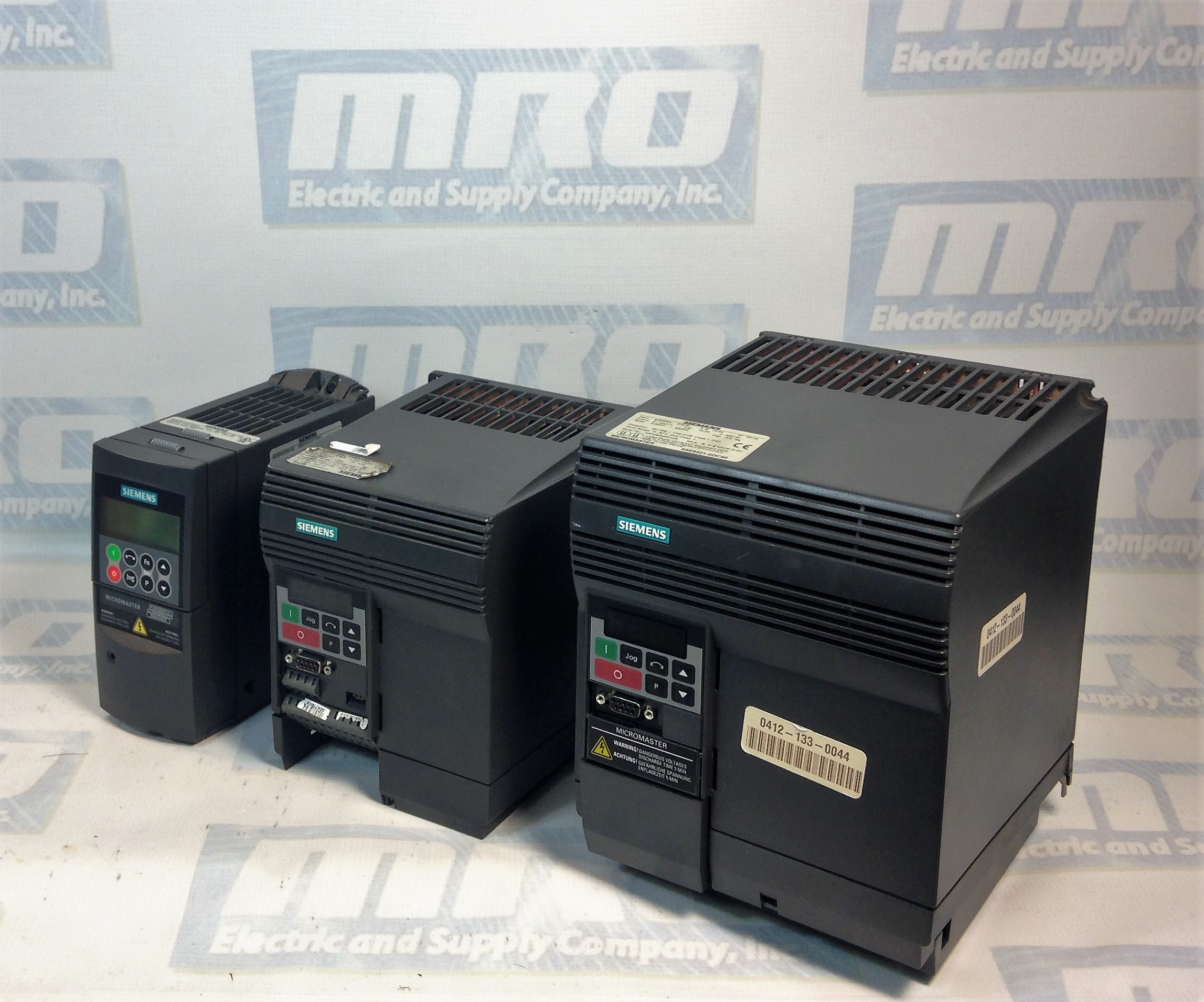
Siemens Micromaster 420: Troubleshooting Faults and Alarms
A blog we posted earlier this week about the Micromaster 420 troubleshooting referenced the Faults and Alarms list for the Micromaster series, so we decided that it would make sense to make the list of Micromaster 420 Faults and Alarms directly available. This is from the corresponding manual for the Micromaster 420 series, but it is buried within the manual which most people most likely don’t even have. Hopefully, this helps with your troubleshooting of Siemens drive fault codes and alarms.
If you’re looking to purchase a Siemens Micromaster drive, view our 420 Micromaster Drives in stock. For more information or to request a quote, please call 800-691-8511 or email sales@mroelectric.com. We also provide pre-priced Micromaster 420 Repairs.
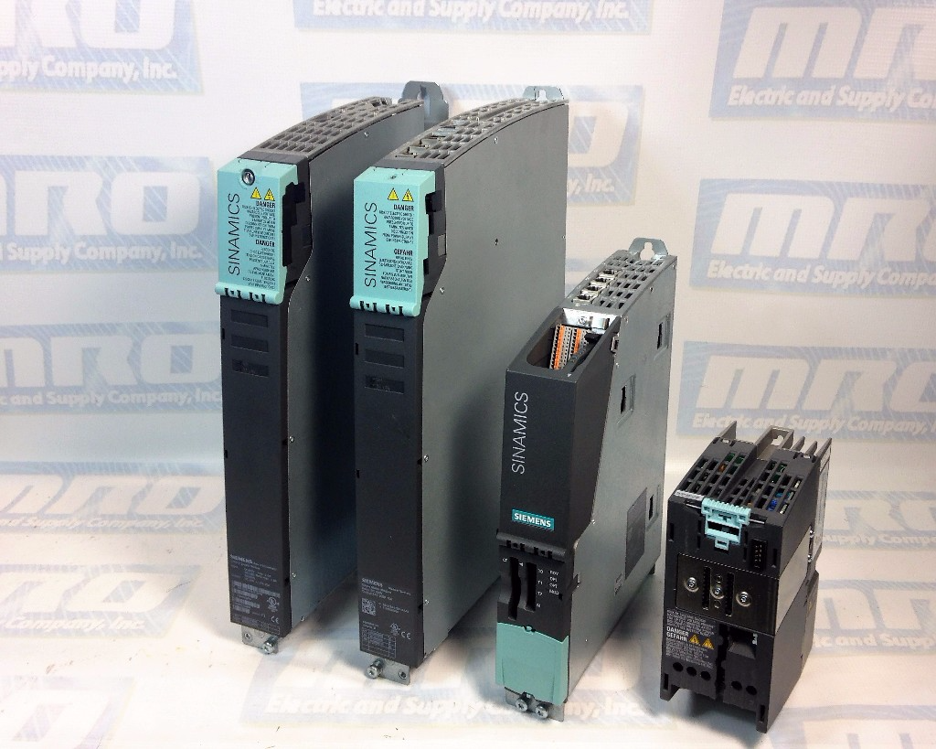
It is important to understand the differences between faults and alarms on Sinamics S120 Drives by Siemens. We have included a list of common faults and alarm codes for S120 drives, what they mean, likely causes and how to fix the fault or alarm. For more Sinamics S120 faults and alarms, check out Part II and Part III of the series that we will be posting shortly. Be sure to check out our website to browse all of our Siemens products.
Understanding Faults
Sinamics S120 Fault Codes Numerical Ranges
When operating Sinamics S120, various errors can arise that may impact the machine’s performance. These faults are typically accompanied by error messages. The fault codes for Sinamics S120 are organized into numerical ranges, each corresponding to a specific type of issue:
F0001 – F0099: Control unit
F0100 – F0199: Reserved
F0200 – F0299: Power supply
F0300 – F0399: Feed unit
F0400 – F0499: Drive
F0500 – F0599: Option board
F0600 – F2999: Reserved
F3000 – F3099: DRIVE-CLiQ component power section
F3100 – F3199: DRIVE-CLiQ component encoder 1
F3200 – F3299: DRIVE-CLiQ component encoder 2
F3300 – F3399: DRIVE-CLiQ component encoder 3
F3400 – F3499: Reserved
F3500 – F3599: Terminal Module 31
F3600 – F4999: Reserved
F5000 – F5039: Communication Board (COMM BOARD)
F5040 – F65535: Reserved
This classification aids in swiftly identifying the type of problem based on the fault code range, making troubleshooting more efficient.
What happens when a fault occurs?
The appropriate fault reaction is initiated
Status signal ZSW1.3 is set.
The fault is entered in the fault buffer.
How are faults eliminated?
Remove the original cause of the fault
Acknowledge the fault
Understanding Alarms
What happens when an alarm occurs?
Status signal ZSW1.7 is set.
Alarms are “Self Acknowledging” meaning they are reset when the cause of the alarm has been eliminated.
List of Sinamics S120 Faults and Alarms
F01000: Internal software error
Message Value: Module: %1, Line: %2 Drive Object:All Objects Reaction: OFF2 Acknowledge: POWER ON Cause: An internal software error has occurred. Fault value (r0949, interpret hexadecimal) Remedy:
Evaluate fault buffer
Carry out a POWER ON (power on/off) for all components.
If required, check the data on the non-volatile memory (memory card).
Message Value: %1 Drive Object:All objects Reaction: OFF2 Acknowledge: POWER ON Cause:An exception occurred during an operation with the FloatingPoint data type. The error may be caused by the basic system or the OA application (e.g. FBLOCKS, DCC). Remedy:
Carry out a POWER ON (power on/off) for all components.
Check configuration and signals of the blocks in FBLOCKS.
Carry out a POWER ON (power on/off) for all components.
Upgrade firmware to a later version.
Contact Service Hotline.
F01003: Acknowledgement delay when accessing the memory
Message Value: %1 Drive Object:All objects Reaction:OFF2 Acknowledge:IMMEDIATELY Cause: A memory area was accessed that does not return a “READY”. Remedy:
Carry out a POWER ON (power on/off) for all components.
Contact Service Hotline
N01004 (F, A): Internal software error
Message Value:%1 Drive Object:All objects Reaction:NONE Acknowledge:NONE Cause:An internal software error has occurred. Remedy:Read out diagnostics parameter (r9999). Reaction upon F: OFF2 Acknowl. upon F: POWER ON Reaction upon A: NONE Acknowl. upon A: NONE
F01005: Firmware download for DRIVE-CLiQ component unsuccessful
Message Value: Component number: %1, fault cause: %2 Drive Object:All objects Reaction: NONE Acknowledge:IMMEDIATELY Cause:It was not possible to download the firmware to a DRIVE-CLiQ component Remedy:
Check the selected component number
Check the DRIVE-CLiQ connection
Save suitable firmware file for download in “/siemens/sinamics/code/sac/”
Use a component with a suitable hardware version
After POWER ON has been carried out again for the DRIVE-CLiQ component, download the firmware again. Depending on p7826, the firmware will be automatically downloaded.
A01006: Firmware update for DRIVE-CLiQ component required
Message Value: Component number: %1 Drive Object: All objects Reaction:NONE Acknowledge:NONE Cause: The firmware of a DRIVE-CLiQ component must be updated as there is no suitable firmware or firmware version in the component for operation with the Control Unit. Alarm value (r2124, interpret decimal): Component number of the DRIVE-CLiQ component Remedy:
Firmware update using the commissioning software:
The firmware version of all of the components on the “Version overview” page can be read in the Project Navigator under “Configuration” of the associated drive unit and an appropriate firmware update can be carried out.
Firmware update via parameter:
Take the component number from the alarm value and enter into p7828.
Start the firmware download with p7829 = 1.
A01007: POWER ON for DRIVE-CLiQ component required
Message Value: Component number: %1 Drive Object:All objects Reaction:NONE Acknowledge:NONE Cause: A DRIVE-CLiQ component must be powered up again (POWER ON) (e.g. due to a firmware update).
Alarm value (r2124, interpret decimal): Component number of the DRIVE-CLiQ component. If the component number is 1, a POWER ON of the Control Unit is required. Remedy:
Switch off the power supply of the specified DRIVE-CLiQ component and switch it on again.
For SINUMERIK, auto commissioning is prevented. In this case, a POWER ON is required for all components and the auto commissioning must be restarted.
A01009 (N): CU: Control module overtemperature
Message Value: – Drive Object:All objects Reaction: NONE Acknowledge:NONE Cause: The temperature (r0037[0]) of the control module (Control Unit) has exceeded the specified limit value. Remedy:
Check the air intake for the Control Unit.
Check the Control Unit fan.
MRO Electric and Supply carries new and used Sinamics modules. For more information or to request a quote, call 800-691-8511 or email sales@mroelectric.com.
Dealing with Sinamics S120 Fault Codes?
Fault codes on your Sinamics S120 can be a major setback. MRO Electric provides the expertise and parts you need to diagnose and resolve issues swiftly, ensuring your drive system runs smoothly without extended downtime.
Relays are an often overlooked, but pivotal component in modern technology, serving as the silent orchestrators behind a wide range of electronic operations. Whether controlling high-power machinery or everyday devices, relays play a crucial role in transferring signals and power without direct electrical connections. They are used across a wide range of devices and applications, from industrial automation to consumer electronics, and understanding how they work is key to fully utilizing their capabilities
Essentially, electrical relays control one electrical circuit by opening and closing contacts in another circuit. When a relay contact is normally open (NO), the circuit is open when the relay is not energized. Conversely, when a relay contact is normally closed (NC), the circuit is closed when the relay is not energized. Applying electrical current to the relay changes the state of these contacts, thereby controlling the connected circuit.
What Is a Relay?
A relay is an electrically controlled switch that has the ability to turn a circuit on or off. Depending on the application relays can do a number of things. Relays can be used as electrical switches to turn things on and off, or as amplifiers to convert smaller currents into larger ones. They can also be used to control a circuit with a low power signal or when multiple circuits need to be controlled by a single signal.
There are two kinds of relays, electromechanical and solid state. In this post, we will be focusing on electromechanical relays and how they work.
Why Are Relays Important?
Electrical relays are crucial because they enable the control of high-current loads using a small amount of electrical current. Relays apply voltage to the coil, which causes a low current to flow through it. This allows a larger current to pass through the contacts and control the electrical load. Relays are essential for applications where low-power control signals need to command high-power circuits.
What Are the Parts of a Relay?
Armature– is a basic metal piece that is balanced on a pivot or a stand. It is considered the moving ‘arm’ of the relay. It makes or breaks the connection with the contacts connected to it.
Spring– is connected to one end of the armature and pushes the armature back into place if no current is passing through.
Electromagnet– is a metal wire wrapped around a metal core. The wire does not have magnetic property but can be converted into a magnet with the help of an electrical signal.
Yoke– is a small metal piece affixedon a core which attracts and holds the armature when the coil is energized.
Contacts– conductive material that exists within the device whose physical contact opens or closes a circuit
A break refers to the number of locations on a circuit that a switch can make or break the flow of current. In electromechanical relays, there can be single breaks and double breaks. A single break is usually used with low power devices while a double break is usually used with high power devices.
A pole refers to the number of circuits that relays can pass through a switch. A single pole contact carries current through one circuit, while a double can carry it through two.
A throw refers to the number of separate wiring paths. For example, a triple throw switch can be connected to one of three contacts instead of one.
In an electromechanical relay, a small circuit has the ability to switch a larger circuit on or off through contacts by using an electromagnet. Some contacts come in different configurations depending on the use of the relay, namely, normally open relays and normally closed relays.
With a normally open (NO) relay, contacts are open when there is no current passing through. Once power is presented, the electromagnet will be activated. When charged, the electromagnet creates a magnetic field that attracts the armature and closes the contacts.
With a normally closed (NC) relay, contacts are closed when there is no current passing through. Unlike normally open relays, when normally closed relays become activated, the circuit will open and cause the current to stop flowing.
What Are the Different Types of Relays?
Electromechanical relays can be broken down into the following distinct categories: general purpose relays, machine control relays and reed relays.
General Purpose Relays
General purpose relays are electromechanical switches that typically function via a magnetic coil. Using an AC or DC current, general purpose relays often run at voltages such as 12V, 24V, 48V, 120V and 230V. Additionally, they can command currents ranging from 2A-30A. These relays are sought after due to them having a multitude of switch configurations and being cost-effective.
Machine Control Relays
Like general purpose relays, machine control relays are operated by a magnetic coil. Typically used to controlstarters and other industrial elements, these relays are robust. While this gives them greater durability, it also means that they are less economical than general purpose relays. However, with additional accessories and functionality, they have an advantage over general purpose relays.
Reed Relays
Reed relays consist of two reeds, which can open or close when controlled by an electromagnet. These small relays can operate up to eight reed switches, which are typically found inside of the electromagnetic coil. When the magnetic force is removed, the reeds return to their initial open position. Since the reeds are only a short distance apart from each other, reed relays work rather quickly. There are many benefits of using a reed relay, as their hermetic seal prevents the passage of contaminants. Additionally, this seal enables reed relays to have dependable switching.
There are many things to consider when choosing a relay for a project. Lifespan, operating environment, mechanical loads, size, and number and type of contacts are all important factors in choosing the right relay.
What Are the Pros and Cons of Using Relays?
While electromechanical relays have a variety of uses, different applications require different automation devices, and electromechanical relays may not always be the best fit. To help you determine if an electromechanical relay will work for you, we have highlighted some of the advantages and disadvantages below.
Advantages
Fast operation and reset
More definitive ON/OFF
Simple and most reliable
Disadvantages
Suffers the effects of age
No directional features
Needs a large amount of input power to operate
What Is a Relay Used For? Relay Applications
Relays protect electrical systems by preventing and reducing the damage to the connected equipment from over currents and voltages. Relays protect a wide range of equipment by detecting and isolating faults in a power transmission and distribution system.
Since electrical relays can control a high-voltage circuit using a low-voltage signal, they can help prevent damage to valuable electronics and components, including modems, amplifiers, and even the starter in your car.
Other applications for relays include:
Automotive
Appliances
Lighting systems
Telecommunication components
Industrial controllers
Electrical power protection systems
Traffic control
How Do You Test a Relay?
While relays are generally dependable, they can still experience faults like any other component. Thankfully, testing a relay is a relatively straightforward process– all you need is a multimeter. Read on to learn how to identify a faulty relay step-by-step.
Locate the relay: Find where the circuits enter and exit the relay. This region is typically marked by pins or terminals.
Check for voltage: With the multimeter set to measure voltage, probe the point where the relay plugs into the circuit. If it does not detect any voltage, inspect the associated fuse or switch for any defects that might interrupt the power supply.
Test ground connection: If voltage is present at the connection point, switch the multimeter to the continuity or resistance function and check for a good ground connection on the opposite side of the relay. A faulty ground can cause the relay to malfunction.
Verify power source: After successfully checking for voltage and testing the ground connection, check the voltage where the relay connects to the battery or another power source. If the multimeter detects no voltage here, it suggests a potential issue with a fuse or circuit breaker.
Test component connection: Use the multimeter’s continuity function to ensure a strong connection between the relay and the component it controls. If continuity exists and the previous steps did not reveal any other faults, it is likely a defective relay.
How Do You Identify a Faulty Relay?
Although relays are considered reliable mechanisms, they do have the capability of failing. Determining whether you have a faulty relay is simple and can be easily identified with the help of a multimeter.
Here are a few tips on how to use your multimeter to test a relay:
Remove the relay from the fuse box or vehicle.
Determine where the input and output points of the circuit are located on the relay.
Make sure your multimeter is set to ohm.
Connect the leads of the multimeter across the entrance and exit pins to determine resistance. Ideally, you’ll see a reading between 50 to 120 ohm.
If your multimeter has a reading of Open or Out of Range you may have a defective coil winding and the relay will need to be replaced.
If the reading looks good, you’ll want to connect the leads in between the switch pins. You should see a reading of OL or Open.
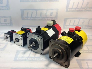
Here are some basic tips on how to test a FANUC servo motor with meter or megohm meter. This procedure will show you how to troubleshoot the servo motor for shorts in windings, cables, or opens. Before starting to test, make sure to turn off all the power sources to the machine and then disconnect the 3-phase motor lines from the drive end. Visually confirm that there are no problems with the cable and then begin testing the servo motor.
How to test your servo motor for a short to ground:
Using an Ohm meter:
Disconnect all power and amplifiers from machine. Check all three wires at T1, T2, and T3 (all three phases) to the ground wire. The readings for this should be infinite, and if it is zero or reads any continuity then there is a problem with the motor or the cable. For this disconnect the cable and check each separately. Be sure to make sure leads on both ends are not touching anything, including the other leads. Most servo motor shorts can be ready with a regular quality meter going to at least 10 megaohms.
Using a Megohm meter:
Disconnect all power from machine. Check all three wires at T1, T2, and T3 (all three phases) to the ground wire. Reading should be between 600-2000 Megohms. Most shorts will be below 20 Megohms. Be careful not to touch the leads or the wires to anything when taking the reading because it can give a false reading. There should be about 1000 Ohms of resistance for each volt of incoming power, but this is not a standard rule. If it is 230meg to 600meg there may be deterioration in the cable.
How to test a servo motor for open or short in the windings:
Using an Ohm meter:
Disconnect all power from the machine. Put meter on ohms and test T1 to T2, T2 to T3, and T1 to T3. The range should be between 0.3 and 2.0 ohms, with most being at about 0.8 ohms. If it is zero there is a short between the two phases. If it is an open the reading will be infinite or well above 2,000 ohms.
Cable and plug notes:
Often times the connector on the cable to the motor will get coolant in it. You can dry it out an retest, if it is still bad the inserts will get burn marks in them and cause a slight short, so they need to be replaced. If it is a DC motor, check the brushes. There should be 3-4 round caps to remove around the motor. Under these there is a spring with a square block (brush). Check to see how much is left, they may need to be replaced.
MRO Electric has a large stock of FANUC servo motors available. If you would like a replacement or spare, or if you have any questions, please call 800-691-8511 or email sales@mroelectric.com. To check out other posts, please visit our blog page.
As a generic name for a plain-text language that CNC machines are able to understand, G-Codes are important to understand in the manufacturing, automation and engineering spaces. You can enter a G-Code manually if you wish, but you do not have to because of the CAD/CAM software’ abilities along with the machine controller. G-Codes are not necessarily readable by humans, but it’s possible to look through the file and determine what is generally occurring.
What Is G Code?
In the factory automation space, nobody likes downtime and receiving error codes. While using CNCs (view FANUC CNC parts here), many professionals are faced with G Codes. By definition, a G Code is a computer code language that is used to guide CNC machine devices to perform specific motions.
What Do CNC G Codes Do?
G Codes are important because they allow easy, repeatable control of the motion of a CNC machine. A few examples of specific motions that CNC G Codes can control, would be:
canned cycles
work coordinates
several repetitive cycles.
Canned Cycles
Also referred to as a fixed cycle, canned cycles are ways to effectively and efficiently perform repetitive CNC machining operations. They automate specific machining functions. A few examples would be pocketing, threading, and drilling. A canned cycle is almost always stored as a pre-program in a machine’s controller. To learn more about canned cycles, check out this article courtesy of zero-divide.net.
Work Coordinates
The G Code coordinate pipeline goes something like this:
Unit conversion to metric
Convert from relative to absolute and polar to Cartesian: g90g91XYZ()
G52, G54, and G92 offsets
G51 scaling
G68 coordinate rotation
G-Code is the most popular programming language used for programming CNC machinery. Some G words alter the state of the machine so that it changes from cutting straight lines to cutting arcs. Other G words cause the interpretation of numbers as millimeters rather than inches. Some G words set or remove tool length or diameter offsets. Be sure to check out our article covering FANUC CNC Codes, including FANUC M Codes, here.
MRO Electric and Supply has new and refurbished FANUC CNC parts available. We also offer repair pricing. For more information, please call 800-691-8511 or email sales@mroelectric.com.
What Are the Different Types of G Code Commands?
Listed below are some easily-understood G-code commands in which are used for setting the speed, feed, and tool parameters.
F= Feed
The F value in G-code is used to set the feed rate, which determines the speed at which the machine’s extruder or tool head moves. F values are typically measured in millimeters per minute (mm/min), so dividing the F value by 60 converts it to millimeters per second (mm/s). For instance, an F value of F1500 means the feed rate is 25 mm/s. The machine operates at this specified feed rate when a G1 command is used, which is essential for precise control of the movement speed.
It is crucial to set the feed rate (F) before the first G1 command to avoid errors. Here’s an example of setting the feed rate:
G1 F1500 X100 Y100
In this example, the machine will move to the coordinates X100 Y100 at a speed of 1500 mm/min (25 mm/s).
S= Spindle Speed
The S command’s purpose is to set the spindle speed. The Spindle speed is almost always set in RPMs (revolutions per minute). Here is an example:
S10000
T= Tool
The T command’s purpose is paired with M6 in order to display the tool number to be used for cutting the current file. Here is an example:
M6 T1
Common G Code Command List
Below is a comprehensive list of common CNC G Codes, designed to guide you through the essential programming for CNC machines.
G311 Power control pre-selection V1, F1, T1/channel 3
G312 Power control pre-selection V2, F2, T2/channel 3
G313 Power control pre-selection V3, F3, T3/channel 3
G314 Power control pre-selection T4/channel 3
G315 Power control pre-selection T5/channel 3
G316 Power control pre-selection T6/pulsing output/Channel 3
G317 Power control pre-selection T7/pulsing output/Channel 3
In conclusion, becoming well-versed on CNC G-Codes, along with other codes associated with CNCs is imperative in this day and age. By having up-to-speed knowledge of CNC codes, you could most definitely set yourself apart from the average Joe.
Below is a chart with fault codes regarding the MagneTek G3 GPD503 series drives. MRO Electric and Supply offers free evaluations on units. You can find our RMA form on our repair page. Follow us on Twitter @MROElectric for updates on new products and find any deals we may have.
bb
External Base Block command
Base Block command at multi-function terminal is active, shutting off GPD 503 output (motor coasting). Temporary condition, cleared when input command is removed.
bUS
Transmission error
Control data cannot be received normally for longer than 2 seconds.
CALL
Communication ready
Drive is waiting for the PLC to establish communication.
CPF00
Transmission error or control function hardware fault (including internal RAM, external RAM or PROM)
Transmission between GPD 503 and remote operator is not established within 5 seconds after the power supply is turned on. (Displayed on the remote operator.)
CPF01
Transmission error
Transmission error occurs 2 seconds or more after transmission has first been established.
CPF02
Base block circuit failure
GPD 503 failure.
CPF03
NV-RAM (S-RAM) fault
GPD 503 failure.
CPF04
NV-RAM (BCC, Access Code)
fault
GPD 503 failure. This fault may be caused after changing EPROM chips. Perform a Sn-03 Reset operation to attempt to clear this fault.
CPF05
A/D converter failure in CPU
GPD 503 failure.
CPF06
Optional connection failure
Improper installation or wiring of option card.
CPF20
A/D converter failure
Defective option card.
CPF21
Transmission interface card (option) self-analysis function fault
Defective option card. Check option card connector for proper installation.
CPF22
Model code fault
Defective option card. Check option card connector for proper installation.
CPF23
Mutual-analysis function fault
Defective option card. Check option card connector for proper installation.
EF (blinking)
Simultaneous forward and reverse operation commands
Fwd Run and Rev Run commands are both closed for more than 500 ms. Removing one command will allow drive operation.
EF0
External fault
GPD 503 is in Stop mode.
EF3
Ext. fault signal at term. 3
A fault condition has occurred in the external circuit(s) monitored by the contact providing input to the indicated terminal. If display is steady, GPD 503 is in Stop mode; if display is blinking, the terminal is programmed to allow continued operation after receiving fault input.
EF5
Ext. fault signal at term. 5
A fault condition has occurred in the external circuit(s) monitored by the contact providing input to the indicated terminal. If display is steady, GPD 503 is in Stop mode; if display is blinking, the terminal is programmed to allow continued operation after receiving fault input.
EF6
Ext. fault signal at term. 6
A fault condition has occurred in the external circuit(s) monitored by the contact providing input to the indicated terminal. If display is steady, GPD 503 is in Stop mode; if display is blinking, the terminal is programmed to allow continued operation after receiving fault input.
EF7
Ext. fault signal at term. 7
A fault condition has occurred in the external circuit(s) monitored by the contact providing input to the indicated terminal. If display is steady, GPD 503 is in Stop mode; if display is blinking, the terminal is programmed to allow continued operation after receiving fault input.
EF8
Ext. fault signal at term. 8
A fault condition has occurred in the external circuit(s) monitored by the contact providing input to the indicated terminal. If display is steady, GPD 503 is in Stop mode; if display is blinking, the terminal is programmed to allow continued operation after receiving fault input.
Err
Constant write-in fault
Temporary display, in Program mode, indicating that constant setting was not written into EPROM memory.
FAn
Cooling fan failure
GPD 503 is in Stop mode.
FU
Fuse blown
DC Bus fuse has cleared. Check for short circuit in output, and check main circuit transistors.
GF
Ground fault protection
Ground current > approx. 50% of the GPD 503 rated current.
oC
Overcurrent
GPD 503 output current exceeds 200% of GPD 503 rated current, or ground fault has occurred, with ground current exceeding 50% of GPD 503 rated current.
oH
Heat sink overheated
Fin temperature exceeds 90° C (194° F)
oH2 (blinking)
External overheat
External temperature monitoring circuit(s) detected an overtemperature condition and produced an input signal.
oL1
Overload
Thermal motor overload protection has tripped.
oL2
Overload
GPD 503 overload protection has tripped.
oL3 (blinking)
Overload
GPD 503 output torque exceeds the set Overtorque Detection level, but GPD 503 is programmed for continued operation at overtorque detection.
oL3
Overload
GPD 503 output torque exceeds the set Overtorque Detection level, and GPD 503 is programmed for coast to stop at overtorque detection.
oPE01
kVA constant setting fault
Sn-01 setting is incorrect.
oPE02
Constant setting range fault
An-XX, bn-XX, Cn-XX, or Sn-XX setting range fault.
oPE03
Constant set value fault
Sn-15 to -18 (multi-function input) set value fault.
oPE04
Constant set value fault
PG constant, number of poles, or PG division rate set incorrectly.
oPE10
Constant set value fault
Cn-02 to -08 (V/f data) set incorrectly.
oPE11
Constant set value fault
One of the following conditions was detected: • Cn-23 > 5 KHz and Cn-24 5 KHz or • Cn-25 > 6 and Cn-24 > Cn-23
ou (blinking)
Overvoltage
Internal monitor of DC Bus voltage indicates that input AC power is excessively high, while GPD 503 is in stopped condition.
ou
Overvoltage (OV)
Detection level: Approx. 400V for 230V; Approx. 800V for 460V; Approx. 1000V for 575V.
rr
Regenerative transistor Failure
Dynamic Braking resistor has failed.
rH
Braking resistor unit overheated
Dynamic Braking resistor has overheated.
Uu (blinking)
Low voltage (Power UV)
Internal monitor of DC Bus voltage indicates that input AC power is below Undervoltage detection level, while the GPD 503 is in stopped condition.
Uu1 Low voltage (Power UV)
Occurs two seconds after detection of low voltage.
Uu2 Low voltage UV
Control circuit voltage levels drop below acceptable levels during operation.
Uu3 Low voltage (MC-ANS fault)
Main circuit magnetic contactor does not operate correctly.