Common UNI1405 Fault Codes

Below is a table of common Unidrive faults found within the Control Techniques Unidrive series, more specifically, the UNI1405. MRO Electric offers core credit on exchanges for new and refurbished units, and have a wide selection of option cards such as the UD51, UD73, and UD77. We also repair Unidrives in-house. Contact us if you are interested in finding a new machine so we can keep your downtime to a minimum!

HF81Software Error (odd address word)
HF82Large option module removed
HF83Power Board Code Failure
HF84Current Offset Trim Failure
HF85A to D failure (ES-CC step)
HF86Interrupt Watchdog failure
HF87Internal ROM check error
HF88Watchdog Failure
HF89Unused Interrupts (nmi as source)
HF90Stack Overflow
HF91Stack Underflow
HF92Software Error (undefined op code)
HF93Software Error (protection fault)
HF94Software Error (odd address word)
HF95Software Error (odd address inst.)
HF96Software Error (illegal ext bus)
HF97Level 1 Noise
HF98Interrupt Crash
HF99Level 1 Crash

Control Techniques Manufacturer Showcase

Established in 1972 in Newtown, Wales, this industrial part manufacturer owned by the Nidec Corporation continues to provide high quality AC Drives and motor control management products today. In this post, we will be showcasing some of the classes and parts Control Techniques has to offer.

Unidrive
The Unidrive line of products from Control Techniques includes devices like brushless AC servo motors. The Unidrive Classic series drives are available in five different sizes and twenty-six different models, allowing you to fit one of these devices in almost any existing automation system. This series of drives have enough built in parameters to meet most task demands.

UNI2403 by Control Techniques

The Unidrive Classic series offers complete I/O configurability, advanced position control, programmable logic functions, regeneration mode for four-quadrant operations, high speed communications for quick feedback, preset macros for simplified operations and more.

Focus DC
The Focus DC line of products are solid state analog DC drives built to last reliably in almost all environments. This family has regenerative models and different enclosure kits available to offer a wide range of custom configurations. Optional kits for these drives include ones that offer toggle switches, signal isolation, M contactor kits, dynamic braking and tachometer feedback modules.

Commander SE
The Commander SE line of products offer flexibility in many automated systems by being the top choice for microdrives. They are built to be rugged machines that can stay physically stable and constantly sit at correct temperatures. These devices are shipped with shipped with firmware that makes first time setup and installation as easy as possible, including the parameters that immediately meet the needs of most drive applications.

Commander SE products by Control Techniques

The Commander SE series offers full control of all levels of parameters, visualization of terminal connections, multiple motor speed preset settings, open loop vector control, fully configurable analog/digital Input/Output settings, sequenced switching between multiple parameters and communications via DeviceNet, PROFIBUS DP and Interbus S.

Unidrive SP
The Unidrive SP series comes in both free-standing and modular forms. The SP modular offers all the benefits of the normal Unidrive SP system along with more intense system power configurations. It is easily able to be connected together to create almost any custom setup necessary. Parallel drives are used together for higher powered motors. These drives are built to last and are flexible.

Some additional modules include SPMA AC in / DC out Drive, SPMC AC in / DC out Rectifier, SPMD DC in / AC out Inverter, SM Control MASTER, SM Control SLAVE, SPM Power Selector.

MRO Electric and Supply offers a variety of new and refurbished Control Techniques devices. We also offer repair pricing. For more information, please call 800-691-8511 or email sales@mroelectric.com.

Control Techniques Commander CDE Trips: Troubleshooting

CDE TRIPS ( MEDIUM / LARGE AND HPCDE )

Control Techniques Commander CDE Trips: Troubleshooting

MRO Electric and Supply has new and refurbished Control Techniques parts available now, and also offers repair pricing. For more information, please call 800-691-8511 or email sales@mroelectric.com.

Control Techniques Commander CDE Trips: Troubleshooting

When a failure occurs with the CDE drive the display will flash a series of segment characters for the trip.

Example: tr iP OU

Commander CDE series stores the past ten failure codes in parameters #10.14 – 10.23 in trip number form. A numeric value trip code is a basic form of the symptom for the technician to work with. These past trips can be accessed via the keypad by entering the value of 149 in the keypad at parameter 00.

Scroll to menu 10, for parameter #10.14 to see a trip number.

Example: 6

Symptom explanations provide an avenue on how to analyze the drive for particular problems.

To make the troubleshooting process easier a chart was created to link the type of trip with the symptom.

TRIP Display | TRIP Number | Symptom

cL 114-20m Loop of current loop 1
Et2External trip contact has opened
I . t3Overload lxt- Sustained Overcurrent
Oh4Heatsink over temperature- Fan Failure ???
OI AC5Instantaneous AC over current trip
OU6DC bus over voltage-Braking Resistor Problem
Ph7AC Supply phase loss
PS8Internal power supply fault
th9Motor thermistor trip-Hot Motor
OI dC10Instantaneous DC over current trip
EPS11External power supply fault +24vdc short?
th512Motor thermistor short circuit
UU13DC bus under voltage
SCL14Serial comms. Loss-Keypad loose/failure
POdL15Loss of Control keypad
cL2164-20mA Loop Loss of current loop 2
cL3174-20mA Loop Loss of current loop 3
EEF18EEPROM
Prc219Processor 2 fault
OA20Ambient over temperature
rS21Stator resistance measurement failure
OUSP22Overspeed Trip
hFPP26-39Hardware Fault
PhPC100AC Supply phase loss from a drive module
OtPC101Over temperature trip in a Drive module
OtPn102-109Over temperature trip in Drive Module #n
PSPn110-117Over voltage trip in Drive Module #n
I OPn118-125Instantaneous Over current in Drive #n
OuPn126-133Over voltage trip in Drive Module #n
dcPn134-141Instantaneous DC current trip in Drive #n
FtYP142Spurious Unidentified trip
ConF143Module Address switches incorrect
8.8.8.8.-I x t trip Warning flashing dots

Emerson Industrial Automation Unidrive SP

Emerson Industrial Automation: Unidrive SP Troubleshooting

Emerson Industrial Automation: Unidrive SP Troubleshooting

Updated August 2019: Click here to view Unidrive fault codes.

DIGITAL INPUTS

The Unidrive SP can be enabled to run in several ways. The drive can use digital inputs, keypad, or a field buss networks to give the OK to run. The drive will display inh, rdy, or run depending on the given commands. The drive can be programmed to use positive or negative logic. The logic type is set up at #8.29 in the Control Techniques Unidrive SP. The Unidrive SP defaults to positive logic. When the drive is in positive logic you will need to inject +24VDC to activate the digital inputs. The +24VDC can be supplied by the drive or externally.

The Unidrive SP can be enabled to run in numerous ways.

When the drive is in the terminal mode the following sequence occurs under default conditions:

Unidrive SP:

Inh = Drive disabled = Connect pins 22-31 drive should go to rdy
Rdy = Drive enabled = Connect pins 22-26 drive should go to run
Run = Drive is enabled and ready to run when a speed reference is applied

Parameter #0.05 sets up the Reference Select. This will tell the drive where to search for run commands and speed references. You will only need to close the enable signal if it is set to pad. Then, the keypad can be used to control the drive and to set the speed reference. The speed reference will come in on an analog input if you choose a terminal code. The digital inputs will select the enable, run, and preset selections. The drive should operate as seen above if the digital inputs are activated correctly.

DRIVE SEQUENCER

When the drive is not running, there are several additional parameters in menu 6 that can assess the issue. The digital inputs may be configured wrong or inactive if the parameters are not going to a 1 with the corresponding commands. Check the following parameters:

#6.15 = 1 = Drive enabled

#6.43 = 1 = Control word disabled, Set to 1 for Field Buss Control

#6.29 = 1 = Hardware Enable (Pin 31 is activated)

#6.30 = 1 = Run Forward #6.31 = 1 = Jog

#6.32 = 1 = Run Reverse

#6.33 = 1 = Forward/Reverse

#6.34 = 1 = Run

#6.37 = 1 = Jog Reverse

#6.39 = 1 = Not Stop

Unidrive SP

The voltage on the corresponding digital inputs should be measured if the parameters in menu 6 aren’t changing state accordingly. The DC voltage should change between 0VDC and 24VDC when a command is given. Check the digital input configuration in menu 8 if menu 6 isn’t changing and the voltage is.

CONTROL WORD

To control the start/stop functions, the drive does not have to use the digital inputs. When #6.43 = 1 the control word is enabled. The drive will now accept a decimal value from 0 to 32767 at #6.42. This decimal value can be converted to a binary value.To see the function that will be carried out, you can reference the binary value to the chart below.

Unidrive SP

Speed Reference

The drive still may not run if the digital inputs and the drive sequencer are each working properly. There could be an issue with the speed reference to the drive if the display shows Run but the motor isn’t turning. The speed reference is able to be applied in several methods. An analog input can be used (current or voltage), preset speeds, and a field buss reference. The example is a 0-10VDC signal on analog input #1.

The final speed of the demand is parameter #3.01. The speed reference should be displayed here if the digital inputs and the drive sequencer are failing to operate properly. Check menu 1 and 2 to determine where it is stopping if the reference is not getting to this point.

If the drive is running in torque mode, the torque reference will come on parameter #4.08 under default conditions. #4.08 is able to be linked to an analog input or be written to via a filed buss network.

Unidrive SP

#7.01 should be inspected to determine if it changes with the change in reference at terminal 5 once the signal has been confirmed. #7.01 goes from +/- 0% – 100%. Check the destination of the speed reference at #7.10 if everything looks good. Follow it to the destination and confirm the speed reference value is arriving there and then through #3.01.

Unidrive SP

Contact the America’s Service Center if the drive will still not run after the Speed Reference, Digital Inputs and Drive Sequencer have all been confirmed.

MRO Electric and Supply has new and refurbished Control Techniques Unidrives available now, and also offers repair pricing. For more information, please call 800-691-8511 or email sales@mroelectric.com.

Emerson Industrial Automation: Unidrive Classic HF Trip Codes

Emerson Industrial Automation: Unidrive Classic HF Trip Codes
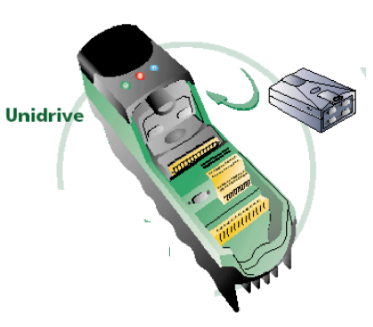
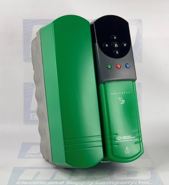
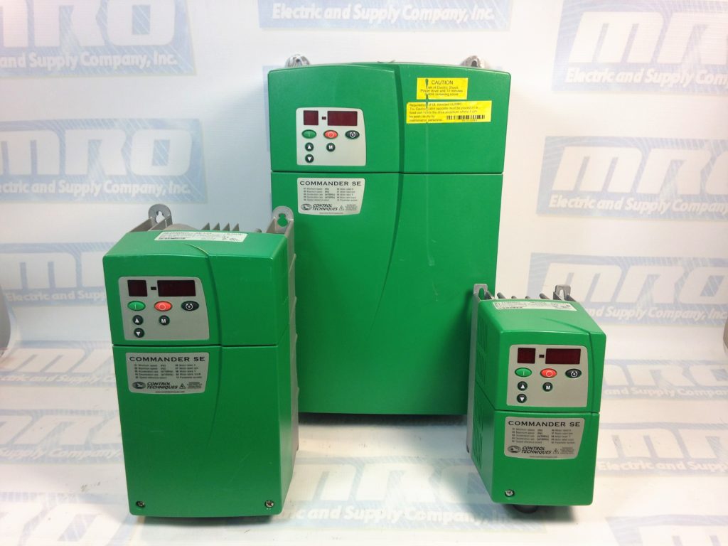
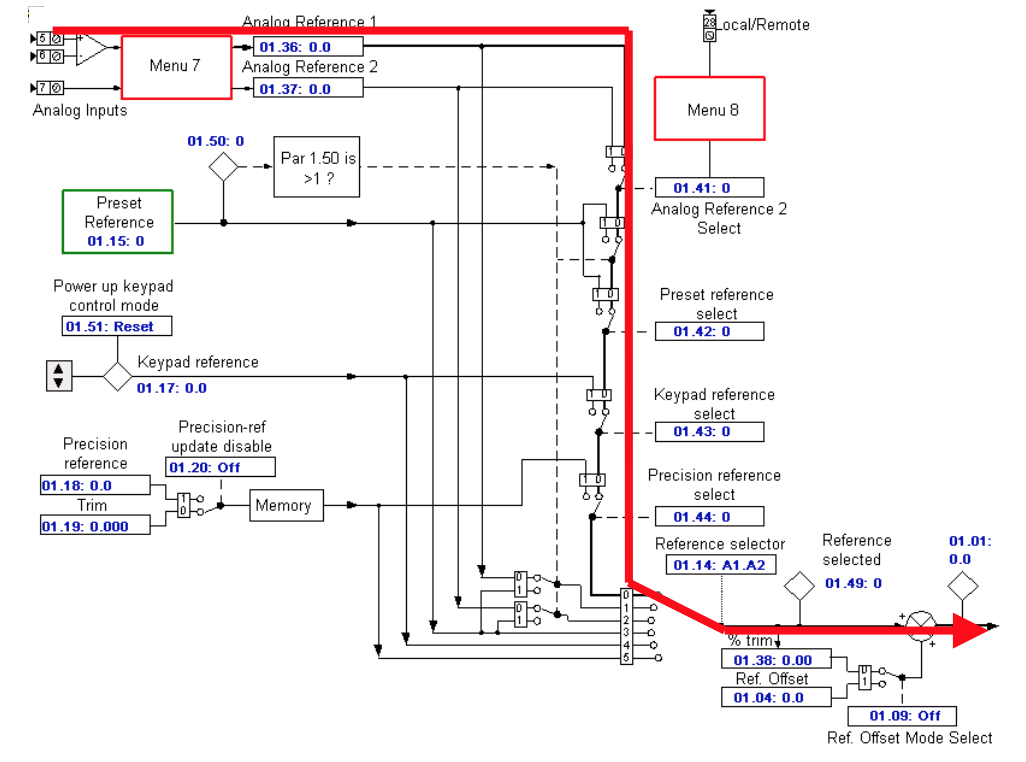
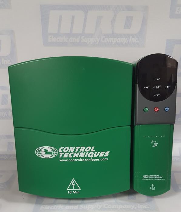
This document is pertinent to all Unidrive Classic models
MRO Electric and Supply has new and refurbished Control Techniques Unidrives  available now, along with our other Control Techniques products. Contact us about pricing for repairs. For more information, please call 800-691-8511 or email sales@mroelectric.com.
Emerson Industrial Automation: Unidrive Classic HF Trip Codes

HF81 Software Error (odd address word)

Unidrive Fault Code DiagnosticsHF81 HF82 HF83 HF84 HF85 HF86 HF87 HF88 HF89 HF90 HF91 HF92 HF93 HF94 HF95 HF96 HF97 HF98 HF99

HF82 Large Option Module Missing

HF83 Power Board Code Failure

HF84 Current Offset Trim Failure

HF85 A to D failure (ES-CC step)

HF86 Interrupt Watchdog failure

HF87 Internal ROM check error

HF88 Watchdog Failure

HF89 Unused Interrupts (nmi as source)

HF90 Stack Overflow

HF91 Stack Underflow

HF92 Software Error (undefined op code)

HF93 Software Error (protection fault)

HF94 Software Error (odd address word)

HF95 Software Error (odd address instruction)

HF96 Software Error (illegal ext bus)

HF97 Level 1 Noise

HF98 Interrupt Crash

HF99 Level 1 Crash

HF Faults are not recorded in the Drive Historical Fault Log

All of the above HF trips in BLUE are typically a result of some sort of hardware failure on the UD90A control PCB. This control board is common to all Unidrive Classics.

For the HF codes in RED refer to the following page

HF82 Large option module missing

If one of the UD7x large option modules is removed, the trip may be expected. There is an issue with either the large option module or the UD90A control PCB if this trip occurs at any other time than the case above.

HF83 Power Board Code Failure

Because the UD90A control PCB was unable to recognize the power rating of the power PCB it is connected to, this trip occurred.

The trip is likely due to the power PCB in the Drive or a problem with the UD90A control PCB on Unidrive Sizes 1 to 4 (which includes UNI1401, UNI1402, UNI1403, UNI1404, UNI1405, UNI2401, UNI2402, UNI2403, UNI3401, UNI3402, UNI3403, UNI3404, UINI3405, UNI4401, UNI4402, UNI4403, and UNI4404).

UD99 PCB or the UD90A PCB cause the trip on a Unidrive Size 5. The interconnects between the PCBs should also be checked, as they could also cause a trip.

HF84 Current Offset Trim Failure

Due to an issue with the current feedback on the drive, this trip occurs. The trip is likely due to the power PCB in the Drive on Unidrive Sizes 1 to 4. An issue with the UD90A control PCB may also cause this trip.

The UD99 PCB or the UD90A PCB cause the trip on a Unidrive Size 5, along with the interconnects between the PCBs.

HF88 Watchdog Failure

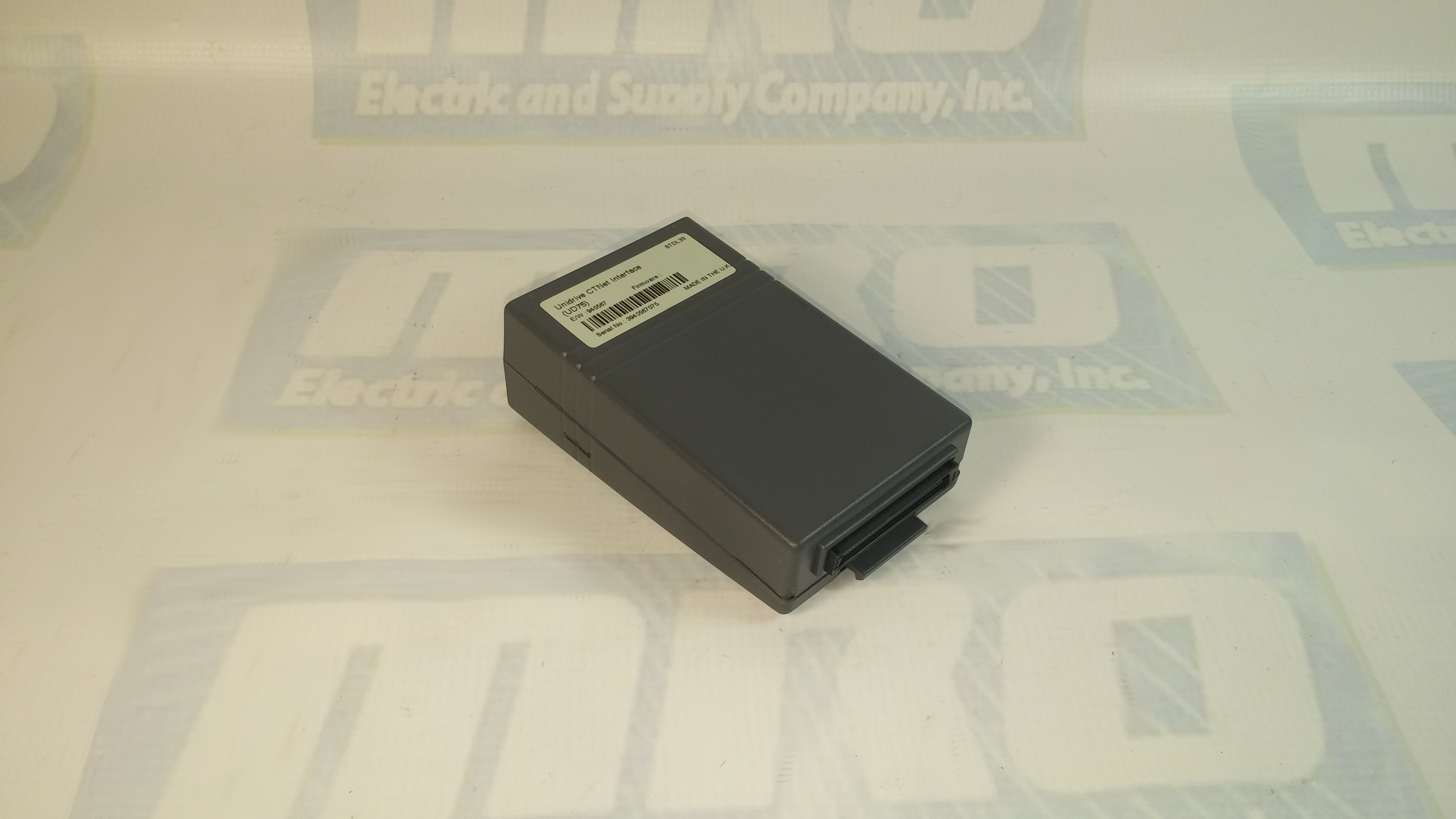
This trip can result from a faulty UD7x Co-Processor. With power off, remove Co-Processor and re-apply power.

HF82 Large option module missing

If one of the UD7x larger option modules is removed while the Drive is powered up, this trip is likely to occur. There is an issue with either the UD90A control PCB or the large option module if this trip were to occur at any other time.

HF83 Power Board Code Failure

The UD90A control PCB was unable to recognize the power rating of the power PCB it is connected to, which is what caused the trip.

The trip is likely due to the power PCB in the Drive on Unidrive Sizes 1 to 4, however, an issue with the UD90A control PCB is also able to cause this trip.

The trip is caused by the UD90A PCB, the UD99 PCB, or the interconnects between the PCBs on a Unidrive Size 5.

HF84 Current Offset Trim Failure

If there is an issue with the current feedback on the Drive, this trip will occur. The trip is likely due to the power PCB in the Drive, but an issue with the UD90A control PCB could also result in a trip on Unidrive Sizes 1 to 4.

On a Unidrive Size 5, the trip is cause by either UD99 PCB or the UD90A PCB. The interconnects between the PCBs could also cause this trip and should be checked.

A trip could be caused by either UD99 PCB, UD90A PCB, or the interconnects between the PCBs on a Unidrive Size 5.

HF88 Watchdog Failure

A faulty UD7x Co-Processor and large option module, ( includes UD70, UD71, UD73, UD74, UD75, and UD76) can cause this trip. Remove Co-Processor and re-apply power with power off.

Unidrive Fault Code DiagnosticsHF81 HF82 HF83 HF84 HF85 HF86 HF87 HF88 HF89 HF90 HF91 HF92 HF93 HF94 HF95 HF96 HF97 HF98 HF99

UNI3404: Beyond the User Manual

The UNI3404 is available with a number of option modules, which increase its flexibility and make it suitable for a very wide range of applications. These modules are briefly described in the following paragraphs. For full details refer to UNI3404 manual that is supplied with each of them. The modules are in two physical formats and are known as Large Option Modules (LOM) and Small Option Modules (SOM). Each Undrive may be fitted with one LOM and one SOM.

Unidrive UNI3404 Large Option Modules
  1. UD78 High Precision Analog Input Module. (LOM):
    • This module provides the following features: a) Infinite resolution analog input for precision speed and position control. Large Option Module Small Option Module 1. Introduction 11 b) RS485 communication port. c) Back up supply connector (requires user provided 24VDC) to maintain power to the drive control circuits and encoder feedback when the 3 phase input to the drive is disconnected.
  2. UD70 Co-Processor Module (LOM)
    • The UD70 is an Intel 960 based co processor module that allows the user to write programs in both IEC1131 ladder / Function Block Diagram and Drive Programming Language (DPL) to provide 1.5 axis motion control and sequence control. This is accomplished using the SyPT programming tool on a PC. The module is fitted with an RS232 programming port for this purpose. It also has an RS485 port for general use and this supports the ANSI protocol as a slave or master controller and ModBus RTU as a slave only.
  3. UD71 Serial Communications Module (LOM)
    • The UD71 provides simple serial communication and has both RS232 and RS485 ports.
  4. UD73 Profibus Interface Module (LOM)
    • The UD73 provides full UD70 co-processor functionality and additionally allows the drive to be connected to a Profibus DP network running at speeds up to 1.5 Mbaud.
  5. UD74 Interbus-S Interface Module (LOM)
    • The UD74 provides full UD70 co-processor functionality and additionally allows the drive to be connected to an Interbus-S network at a fixed data rate of 500 Kbaud.
  6. UD75 CTNet Interface Module (LOM)
    • The UD75 provides full UD70 co-processor functionality and additionally allows connection to a CTNet nework. CTNet is Control Techniques fully de-centralized peer to peer fieldbus. This allows implementation of a fully distributed control system with no central PLC controller required.
  7. UD76 Modbus Plus Interface Module (LOM)
    • The UD76 provides full UD70 co-processor functionality and additionally allows connection to a Modbus Plus network.
  8. UD77 DeviceNet interface module (LOM)
    • The UD77 provides full UD70 co-processor functionality and additionally allows connection to a DeviceNet network.
  9. CAN interface module
    • This is based on the UD77 hardware but has different firmware to allow the user to communicate through the CAN physical layer but using his own protocol written using the SyPT toolkit.
  10. CanOpen interface module
    • This is based on the UD77 hardware but the firmware is changed so that the network uses the CanOpen protocol.
Unidrive UNI3404 Small Option Modules
  1. UD50 Extended I/O module
    • This module provides the following additional I/O capability:
      • a) qty. 3, 24VDC digital inputs.
      • b) qty. 3, dual function (user selectable) 24VDC digital inputs / outputs. Rated at 30mA when configured as outputs.
      • c) qty. 2, 10 bit plus sign analog inputs +10 to –10VDC
      • d) qty. 1, analog output +10 to –10VDC.
  2. UD51
    • Second encoder module In servo mode this provides the drive with the following additional capabilities:
      • a) Allows use of a second incremental encoder as a master reference input for digital lock, Electronic Gear box and camming functions.
      • b) Alternatively the UD51 may be configured for frequency and direction input to be used as the drive speed reference.
  3. UD52 Sin/Cos encoder module
    • The UD52 allows a servomotor fitted with a sin/cos encoder to be used. This provides an interpolated resolution of up to 1,048,576 ppr when used with a 512 pulse sin cos encoder and also allows use of an optional 4096 revolution absolute encoder. The Unimotor is available with these encoders fitted as a standard option.
  4. UD53 Resolver Module
    • The UD53 allows use with a servomotor having resolver feedback. This is much more rugged than an encoder and therefore suitable for use in harsh environments. The UD53 can operate with resolver having either 2:1 or 3:1 turns ratio (primary : secondary)
  5. UD55 Cloning Module
    • The cloning module is intended to make it possible to copy up to 8 different parameter sets and subsequently load any of these onto another drive. It is useful in a production environment when many drives have to be set up with the same parameters. Unlike the other small option modules it is not normally left permanently installed in a drive.

Contact us today for an instant quote on any Control Techniques Unidrive, small option module, or large option module at 1-800-691-8511 or at sales@mroelectric.com

uni3404
UNI3404

UD75 Configuration and Setup

You can check out our previous blog post  on the UD75 here for more information. Check out the UD75 product page on our website along with all of our other Unidrive options.

UD75 Configuration
  1. Isolate the drive from the mains supply and allow 5 minutes for the DC Bus capacitors to discharge.
  2. Insert Large Option Module as shown below. Ensure that it is correctly inserted. The module will click firmly into place.
  3. To remove the module, pull on the black tab, and the module will disengage from the connector and pull out of the drive.
UD75 Configuration: Cable Screen
The screen of the cable at every node on the network MUST be connected to the screen terminal (pin 3) on the CTNet terminal block. When the screen is stripped back to connect the twisted pair to the CTNet terminals, keep the exposed section of the cable as short as possible. On the CTNet PC Interface Adapter Card, there is no screen terminal. The screen should be cut and taped back to prevent it coming into contact with any other surfaces. The on-board terminal resistor should not be connected.
UD75 Configuration: Network Termination
The network MUST be fitted with terminating resistors AT BOTH ENDS!!! If resistors are not fitted, the network appear to work OK, but the noise immunity of the network will be drastically reduced. The terminating resistor value should match the nominal characteristic impedance value for the cable; in the case of the customized CTNet cable, the terminating resistors used should be nominally 78Ω. PC ISA and PCMCIA cards for interfacing a PC to CTNet are available from CT SSPD.

For price and ordering info you can email sales@mroelectric.com or call 1-800-691-8511. We have these and all the other Control Techniques Unidrive Classic option modules in stock, along with the drives themselves.

UD75 Configuration
UD75 Configuration