The modern landscape of industrialization is a chaotic mix of unnatural speed, precise accuracy, and unprecedented efficiency. This in large is thanks to the development of Automated Material Handling (AMH). AMH has emerged as a game-changing technology that optimizes the movement, storage, and control of materials within manufacturing, warehousing, and distribution environments. By leveraging robotics, artificial intelligence (AI), and advanced software systems. AMH reduces human intervention, minimizes errors, and enhances productivity.
What is AMH?
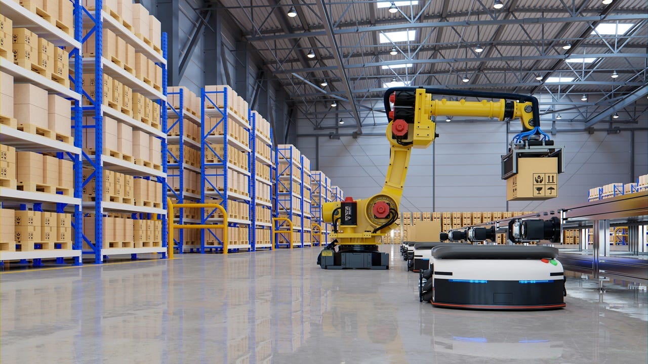
In short, AMH refers to the use of computerized and robotic systems to transport, store, and retrieve materials with minimal human involvement. Some examples of these systems include, conveyor systems for fast and efficient transport of materials across warehouses. Self-navigating robots/vehicles that can move materials around autonomous. These robots can also be paired with advanced storage systems to me retrieval a more streamlined process. Additionally robotic arms can quickly and safely pick up items that would normally be too heavy for one person to life. Robotic arms also serve a crucial role in automated assembly.
The Importance of AMH
Automated Material Handling is a relatively new system that would make it easy to dismiss. However, in the short time it’s been around, it has made its role in automation absolutely crucial in keeping up with demand. On average, businesses that integrate AMH see about a 7.9% uptick in their annual growth. Of course speed is not the only factor that plays into this growth. Automating material handling reduces labor cost and increases efficiency with less margins of error.
While the initial cost of Automated Material Handling is undeniably high, the reduced labor, saving of space, and higher accuracy count makes it a great long term return on investment (ROI).
On a more technological level, AMH is designed to be scalable and upgradable integrating newer technologies such as AI. As a business grows, the operational space and systems are easily expandable to match that the pace and demands of that business. Likewise, AI-driven analytics ensure live tracking of inventory and orders.
Who Benefits from AMH
When we talk about industries that benefit most from automated material handling, manufacturing and retail tend to be at the forefront of what everyone thinks. AMH speeds up the manufacturing process in times that would take a team much longer to do. At the same time, the retail world utilizes AMH for rapid order fulfillment and warehouse distribution.
However, the pharmaceutical industry also utilizes AMH for handling hazardous materials and other substances. At the same time the food and beverage industry uses automated machine handling to keep their products at safe and preferable temperatures.
Conclusion
Automated Material Handling is no longer a luxury but a necessity for industries aiming to boost efficiency, cut costs, and stay competitive. By integrating AMH solutions, businesses can achieve faster operations, higher accuracy, and a safer work environment—paving the way for a smarter, more automated future.
Need Equipment?
Are you looking to get your automated? Perhaps you already are automated but need to get some parts replaced? Reach out to our team of experts to help connect you with the right equipment to get your operation up and running!