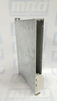
Siemens Sinamics TM120 Terminal Module: Beyond the User Manual

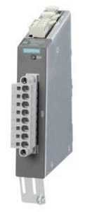
Terminal Modules are used to add further input and output interfaces to the S120 drive system. Terminal Modules are connected to the Control Unit using DRIVE-CLiQ.  DRIVE-CLiQ is a proprietary networking system by Siemens that aims to prevent packet loss and removes some of the collision handling capability. This allows for a high speed deterministic system, but also means that the protocol is not suitable for wireless or slip-ring communication. The TM120 module is used in evaluating temperatures. The temperature is monitored for the following sensors:

  • PT100
  • PT1000
  • KTY84
  • Bimetallic NC contact

The TM150 features 2 DRIVE-CLiQ interfaces, 4 temperature sensor inputs, and one power supply.

tm120

The part number for the Siemens SINAMICS TM120 terminal module is 6SL3055-0AA00-3KA0.

The SINAMICS TM120 is just one of many additional components that are available for S120 systems. These control units significantly reduce system costs, as they increase functionality for positioning, safety integration, and drive control allowing all these functions to be controlled by one unit versus several. There is also additional flexibility with a high number of programming options and digital inputs. With up to 12 binary inputs, the modules’ high I/O count add ease of use. The additional Ethernet port expands programming options as well.

Does your Siemens SINAMICS TM120 module need to be serviced? As with all of our services, our repairs come with a 12 month guarantee. Our repair service is based on doing the right job, and getting your part back to you as soon as possible. Every part we refurbish is tested to make sure they work the way they are supposed to. Our factory-trained technicians have many years working with Siemens products. Minimize your future downtime today by contacting MRO Electric and Supply right now.

MRO Electric stocks new and refurbished TM120 modules. If you would like a replacement module, please call 800-691-8511 or email sales@mroelectric.com.

Siemens Sinamics CU130 Modules: Beyond the User Manual

The CU130 is an S120 single axis control unit capable of controlling PM340 Power Modules. It clips onto the front of the power module and must be used in conjunction with this. The two versions of the CU130 that were released included the CU130 DP PROFIBUS interface and the CU130 PN PROFINET interface. The respective part numbers include:

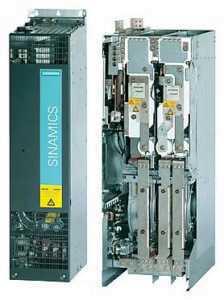
All SINAMICS versions are based on a platform concept. Joint hardware and software
components, as well as standardized tools for design, configuration, and commissioning
tasks ensure high-level integration across all components. SINAMICS handles a wide variety of drive tasks with no system gaps. Different SINAMICS versions can be easily
combined with each other.

The following system components are available:

  • Line-side power components, such as fuses, contactors, reactors, and filters
  • Line Modules, which supply power centrally to the DC link
  • DC-link components (optional), which stabilize the DC-link voltage
  • Motor Modules, which act as inverters, receive power from the DC link, and supply the connected motors

SINAMICS is a new series of drives from Siemens designated for the following mechanical and plant engineering applications:

  • Simple pump and fan applications
  • Complex individual drives in centrifuges, presses, extruders, elevators, as well as
    conveyor and transport systems
  • Drive line-ups in textile, plastic film, and paper machines
  • Highly dynamic servo drives for machine tools

Depending on the application, the SINAMICS range offers the ideal version for any drive
task.  Users can choose from many different harmonized components and functions to create a solution that best meets their requirements. MRO Electric and Supply has all of your Siemens needs including SINAMICS, SIMODRIVE, and SINUMERIK modules.

MRO Electric stocks both new and refurbished CU130 Control Units, which is part number 6SL3310-1GE36-1AA3. If you would like to purchase a replacement module, please call 800-691-8511 or email sales@mroelectric.com.

Siemens’ Update Broadens Toolset for Digitization in Machine Shop Environments

Siemens CNC

Siemens’ Update Broadens Toolset for Digitization in Machine Shop Environments

The most recent update from Siemens’ NX software coalesces the next generation of tools concerning additive manufacturing, CNC (computer numeric control) machining, robotics, and, last but not least, quality inspection to enable the digitalization of part manufacturing within a single, cohesive end-to-end system.

Up-to-date automation competence for computer-aided manufacturing (CAM), including robotic programming, adaptive milling, and tooling design, provide innovative, industry-specific technology to help deliver high-quality products to the market in less time. The new NX Machining Line Planner tool, combined with integrated NX CAM software for feature-based machining, provides new capabilities for industries with high-volume production of complicated parts, such as automotive and industrial machinery. The latest version of NX continues to support end-to-end solutions for additive manufacturing, helping manufacturers realize the goal of using 3D printing for industrial production.

Part manufacturers proceed to face increased pressures from modified market expectations, with customers who require optimized accuracy and faster response times. In order to remain competitive, many part manufacturers look to digitalization, which connects all of the steps of part manufacturing planning and production with a single source of information, or a digital thread. Implementing a digital strategy can enable part manufacturers of all sizes to take greater advantage of automation, adopt 3D printing for production, and ultimately expand into new market opportunities and reduce time to delivery.

State-of-the-art automation enhancements within the latest version of NX provide powerful ways to expand production efficiency and decrease cost. Robotic programming technology provides the ability to automate complete manufacturing cells, including programming robots to perform machining. Adaptive milling and tube milling are new capabilities that provide innovative ways to automate CNC machines and accelerate cutting of complex parts. Adaptive milling is a high-speed cutting method that leverages automation within NX to decrease machining cycles by up to 60 percent while extending tool life. Tube milling streamlines the 5-axis programming process by eliminating preparation and minimizing inputs, utilizing advanced capabilities to create ideal tool paths and minimize errors in machining on the shop floor.

Mold and die manufacturers can now accordingly dictate tool production costs through integration between NX and the Teamcenter portfolio. Engineers can now use NX to automatically recognize features and parameters on the desired part, and provide pertinent information to Teamcenter, which can precisely calculate the tool cost. The newly integrated capabilities of Siemens’ product lifecycle management (PLM) software solutions can enable tool manufacturers to win more orders and increase profit margins through automated costing and accurate quotations.

New to this version, NX Machining Line Planner, combined with integrated NX CAM, enables the feature recognition, distribution, balancing, programming and simulation of operations over multiple setups and machines. Particularly helpful for industries with high-volume production of complicated parts with many features, NX Machining Line Planner uses a digital twin of the complete machining line and NX CAM feature-based machining technology to optimize the entire process. NX Machining Line Planner, combined with the power of the digital twin, offers a truly unique solution that enables automotive and machinery manufacturers to reduce planning time and increase overall production results.

The newest version also inflates the new additive manufacturing solution in NX by including the new module, NX AM for HP Multi Jet Fusion, which is certified by HP and powered by Materialise, to prepare print jobs for HP Jet Fusion 4200 3D printers. The NX software module will allow customers to develop and manage parts in a single software environment for Multi Jet Fusion printing solutions, avoid costly and time-consuming data conversions and third-party tools, and improve their overall design-to-finished-part workflow efficiency.

Additionally, Siemens develops applications for additive manufacturing process simulation in Simcenter 3D, a crucial tool to help manufacturers industrialize additive manufacturing by printing components the first-time-right. These simulation applications are an integral part of the Siemens’  additive manufacturing solution. Increasing productivity is one goal for most of those in the automation space (check out boosting factory automation productivity here). MRO Electric and Supply has new and refurbished Siemens products available. We also offer repair pricing. For more information, please call 800-691-8511 or email sales@mroelectric.com.

6sn1123-1ab00-0ca1

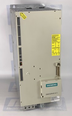
Siemens Simodrive 6SN1123-1AB00-0CA1 Power Supply Module

The Siemens Simodrive 6SN1123-1AB00-0CA1 is a 2 Axes, 50 Amp Power Module with internal cooling. The module’s motor rated current for the 1FT5 series is 25 A, and 18 A for the 1FT6 series. However, the power module can be used with a variety of Siemens and third-party motors. The 6SN1123-1AB00-0CA1 is also equipped with overload protection , which prevents motors and cables from being overloaded.

The 6SN1123-1AB00-0CA1 is part of the Simodrive 611 Converter System that can be used for a variety of purposes, including machine tools, robots and manipulators, mass production, form and tool construction, presses and packing machines, and production machines for glass, wood, stone, and textile. The Simodrive’s compact and modular nature allow it to be used for a variety of manufacturing solutions, and can be easily expanded whenever necessary.

Here are the overall specs for the 6SN1123-1AB00-0CA1:

For Operation of Induction Motors
Nominal Current (A eff): 24
Current for S6-40% (A eff): 32
Peak Current (A eff): 32
Inverter Pulse Frequency (kHz): 3.2
Derating Factor XL (%): 55
Power Loss Total (W): 538
Power Loss Internal (W):184
Power Loss External (W): 250
For Operation of Synchronous Motors
Nominal Current (A eff): 18
Peak Current (A eff): 36
Inverter Pulse Frequency (kHz): 4
Derating Factor XL (%): 55
Power Loss Total (W): 380
Power Loss Internal (W):130
Power Loss External (W): 250
General Technical Data for the Regulated Infeed:
Input Voltage (V DC): Regulated – 600V or 625V  DC; Unregulated- U DC Link=U Supply*1.35.
Maximum Output Voltage (V eff): U a_max = (U DC Link / 1.4)
Minimum Motor Current (A): 3.6
Transistor Limit Current (A): 50
Efficiency: 0.98
Module Width (mm): 100
Weight approx. (kg): 13.5
Maximum Air Flow of Fan (Volumetric Flow m3/hr): 56
Motor Connection: Connectors

The 6SN1123-1AB00-0CA1 can be operated as both a regulated and unregulated power supply for the drives.

MRO Electric has new and refurbished 6SN1123-1AB00-0CA1 Power Modules available. For more information or to request a quote, please call 800-691-8511 or email sales@mroelectric.com.

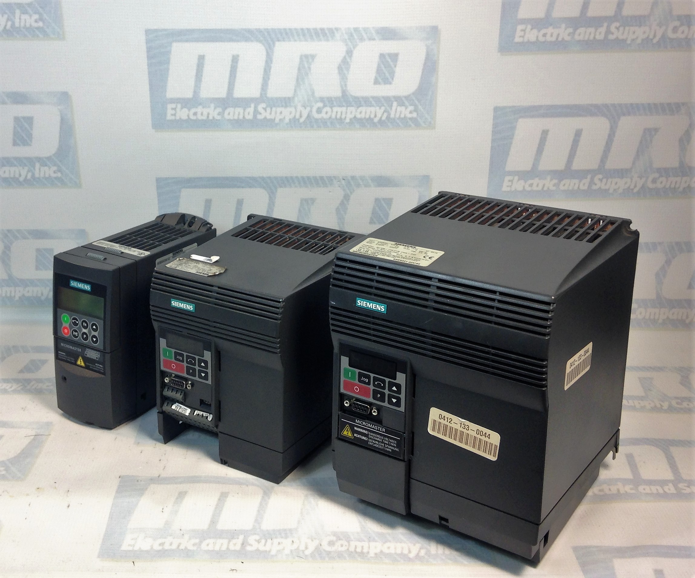
micromaster 440

MicroMaster 440 Parameter List and Fault Codes

Optimize the functionality of your Siemens Micromaster 440 by checking out our parameter list and guide to understanding Micromaster 440 fault codes and alarms.

MRO Electric has new and refurbished Micromaster 440 Drives in stock. Take a look at all of our Siemens products including motors, drives, HMIs, and much more. Be sure to check out our list of Siemens Micromaster 420 fault codes as well.  

If you need assistance with your Micromaster 440, our team can also repair non-functioning drives. To request a quote, please email sales@mroelectric.com or call 800-691-8511.

Micromaster 440 Parameter List

Following parameters are needed for quick commissioning of a Micromaster 440 drive.
NoNameAccess levelCstat
P0100 Europe / North America1C
P0205Inverter application3C
P0300Select motor type2C
P0304Motor voltage rating1C
P0305Motor current rating1C
P0307 Motor power rating1C
P0308Motor cosPhi rating2C
P0309 Motor efficiency rating2C
P0310Motor frequency rating1C
P0311Motor speed rating1C
P0320 Motor magnetizing current3CT
P0335Motor cooling2CT
P0640 Motor overload factor [%]2CUT
P0700Selection of command source1CT
P1000Selection of frequency setpoint1CT
P1080Min. speed1CUT
P1082Max. speed1CT
P1120Ramp-up time1CUT
P1120Ramp-down time1CUT
P1135 OFF3 ramp-down time2CUT
P1300Control mode2CT
P1500 Selection of torque setpoint2CT
P1910Select motor data identification2CT
P3900 End of quick commissioning1C

Micromaster 440 Faults and Alarms

In the event of a failure, the inverter switches off and one of the following fault codes appear on the display.
FaultPossible CausesDiagnose & RemedyQuit
F0001
OverCurrent
- Motor power (P0307) does not correspond to the inverter power (r0206)
- Motor lead short circuit
- Earth faults
Check the following:
1. Motor power (P0307) must correspond to inverter power (r0206).
2. Cable length limits must not be exceeded.
3. Motor cable and motor must have no shortcircuits or earth faults
4. Motor parameters must match the motor in use
5. Value of stator resistance (P0350) must be correct
6. Motor must not be obstructed or overloaded
- Increase the ramp time
- Reduce the boost level
OFF2
F0002
OverVoltage
- DC-link voltage (r0026) exceeds trip level (P2172)
- Overvoltage can be caused either by too high main supply voltage or if motor is in regenerative mode. Regenerative mode can be cause by fast ramp downs or if the motor is driven from an active load.
Check the following:
1. Supply voltage (P0210) must lie within limits indicated on rating plate .
2. DC-link voltage controller must be enabled (P1240) and parameterized properly.
3. Ramp-down time (P1121) must match inertia of load.
4. Required braking power must lie within specified limits.
NOTE:
Higher inertia requires longer ramp times; otherwise, apply braking resistor.
OFF2
F0003
UnderVoltage
- Main supply failed.
- Shock load outside specified limits.
Check the following:
1. Supply voltage (P0210) must lie within limits indicated on rating plate.
2. Supply must not be susceptible to temporary failures or voltage reductions.
OFF2
F0004
Inverter Over
Temperature
- Inverter overloaded.
- Duty cycle too demanding.
- Motor power (P0307) exceeds inverter power capability (r0206).
Check the following:
1. Load duty cycle must lie within specified limits.
2. Motor power (P0307) must match inverter power (r0206)
OFF2
F0011
Motor Over
Temperature
- Motor overloaded Check the following:
1. Load duty cycle must be correct
2. Motor nominal overtemperatures (P0626-P0628) must be correct
3. Motor temperature warning level (P0604) must match
OFF1
F0012
Inverter temp.
signal lost
Wire breakage of inverter temperature (heatsink) sensorOFF2
F0015
Motor temperature
signal lost
Open or short circuit of motor temperature sensor. If signal loss is detected, temperature monitoring switches over to monitoring with the motor thermal model.OFF2
F0020
Mains Phase
Missing
Fault occurs if one of the three input phases are missed and the pulses are enabled and drive is loadedCheck the input wiring of the mains phasesOFF2
F0021
Earth fault
Fault occurs if the sum of the phase currents is higher than 5 % of the nominal inverter current.
NOTE - Framesizes D to F
This fault only occurs on inverters that have 3 current sensors.
OFF2
F0022
Powerstack fault
That hardware fault (P0947 = 22 and
P0949 = 1) caused by the following events:
(1) DC-link overcurrent = short circuit of IGBT
(2) Short circuit of chopper
(3) Earth fault
(4) I/O board is not poperly inserted.
- Framesizes A to C (1),(2),(3),(4)
- Framesizes D to E (1),(2),(4)
- FramesizeF(2),(4)
- Since all these faults are assigned to one signal on the power stack, it is not possible to establish which one actually occurred.
- UCE failure was detected, when P0947 = 22 and fault value P0949 =12 or 13 or 14, depending on UCE (for MegaMaster only)
Check the I/O board. It has to be fully pressed home. OFF2
F0023
Output fault
One phase of output is disconnectedOFF2
F0024
Rectifier Over
Temperature
- Ventilation inadequate
- Fan inoperative
- Ambient temperature is too high.
Check the following:
- Fan must turn when inverter is running
- Pulse frequency must be set to default value
- Ambient temperature could be higher than
specified for the inverter
OFF2
F0030
Fan has failed
Fan no longer working- Fault cannot be masked while options module
(AOP or BOP) is connected.
- Need a new fan.
OFF2
F0035
Auto restart after n
Auto restart fault after n-restart tryOFF2
F0040
Automatic
Calibration Failure
MICROMASTER 440 onlyOFF2
F0041
Motor Data
Identification
Failure
Motor data identification failed.
- Alarm value =0: Load missing
- Alarm value =1: Current limit level reached during identification.
- Alarm value =2: Identified stator resistance less than 0.1% or greater than 100%.
- Alarm value =3: Identified rotor resistance less than 0.1% or greater than 100%.
- Alarm value =4: Identified stator reactance less than 50% and greater than 500%
- Alarm value =5: Identified main reactance less than 50% and greater than 500%
- Alarm value =6: Identified rotor time constant less than 10ms or greater than 5s
- Alarm value =7: Identified total leakage reactance less than 5% and greater than 50%
- Alarm value =8: Identified stator leakage reactance less than 25% and greater than 250%
- Alarm value =9: Identified rotor leakage inductance less than 25% and greater than 250%
- Alarm value = 20: Identified IGBT onvoltage less than 0.5 or greater than 10V
- Alarm value = 30: Current controller at voltage limit
- Alarm value = 40: Inconsistence of identified data set, at least one
identification failed Percentage values based on the impedance Zb = Vmot,nom / sqrt(3) / Imot,nom
0: Check that the motor is connected to the inverter.
1-40: Check if motor data in P304-311 are correct. Check what type of motor wiring is required (star, delta).
OFF2
F0042
Speed Control
Optimisation Failure
- Motor data identification failed.
- Alarm value =0: Time out waiting for stable speed
- Alarm value =1: Inconsistent readings
OFF2
F0051
Parameter EEPROM
Fault
- Read or write failure while saving nonvolatile
parameter.
- Factory Reset and new parameterization
- Change drive
OFF2
F0052
power stack Fault
- Read failure for power stack information or invalid data- Change driveOFF2
F0053
IO Eeprom Fault
- Read failure for IO EEPROM information or invalid data.- Check data
- Change IO module
OFF2
F0054
Wrong IO Board
1. Wrong IO board is connected.
2. No ID detected on IO board, No data.
- Check data
- Change IO module
OFF2
F0060
Asic Timeout
- Internal communications failure- If fault persists, change inverterOFF2
F0070
CB setpoint fault
- No setpoint values from CB (communication board) during telegram off time- Check CB and communication partnerOFF2
F0071
USS (BOP-link)
setpoint fault
- No setpoint values from USS during telegram off time- Check USS masterOFF2
F0072
USS (COMM link)
setpoint fault
- No setpoint values from USS during telegram off time- Check USS masterOFF2
F0080
ADC lost input
signal
- Broken wire
- Signal out of limits
OFF2
F0085
External Fault
- External fault triggered via terminal inputs- Disable terminal input for fault trigger.OFF2
F0090
Encoder feedback
loss
- Signal from Encoder lost1. Check encoder fitted. If encoder not fitted, set P400 = 0 and select SLVC mode (P1300 = 20 or 22)
2. Check connections between encoder and inverter
3. Check encoder not faulty (select P1300 = 0, run at fixed speed, check encoder feedback signal in P66)
Increase encoder loss threshold in P492
OFF2
F0101
Stack Overflow
- Software error or processor failure- Run self test routinesOFF2
F0221
PID Feedback below
min. value
- PID Feedback below min. value P2268- Change value of P2268.Adjust feedback gain.
F0222
PID Feedback above
max. value
- PID feedback above max. value P2267.- Change value of P2267.Adjust feedback gain.
F0450
BIST Tests Failure
Fault value:
1. Some power section tests have failed
2. Some control board tests have failed
4. Some functional tests have failed
8. Some IO module tests have failed. (MM 420 only)
16. Internal RAM failed on power-up check
- Drive may run but some features will not work properly.
- Replace drive.
F0452
Belt Failure
Detected
- Load conditions on motor indicate belt
failure or mechanical fault.
Check the following:
1. No breakage, seizure or obstruction of drive train.
1. If using an external speed sensor, check for correct function.Check parameters:
- P0409 (pulse per min at rated speed).
- P2191 (Belt failure speed tolerance).
- P2192 (delay time for permitted deviation)
2. If using the torque envelope, check parameters:
- P2182 (threshold frequency f1)
- P2183 (threshold frequency f2)
- P2184 (threshold frequency f3)
- P2185 (upper torque threshold 1)
- P2186 (lower torque threshold 1)
- P2187 (upper torque threshold 2)
- P2188 (lower torque threshold 2)
- P2189 (upper torque threshold 3
- P2190 (lower torque threshold 3)
- P2192 (delay time for permitted deviation)
4. Apply lubrication if required.

Need help with your Micromaster 440 drive?

Navigate through complex Micromaster 440 parameters and fault codes with ease. MRO Electric offers comprehensive support, from detailed parameter lists to expert repair services, ensuring your drive operates at peak performance.

sinumerik 840d sl

Siemens SINUMERIK 840D SL: Product Spotlight & Alarms

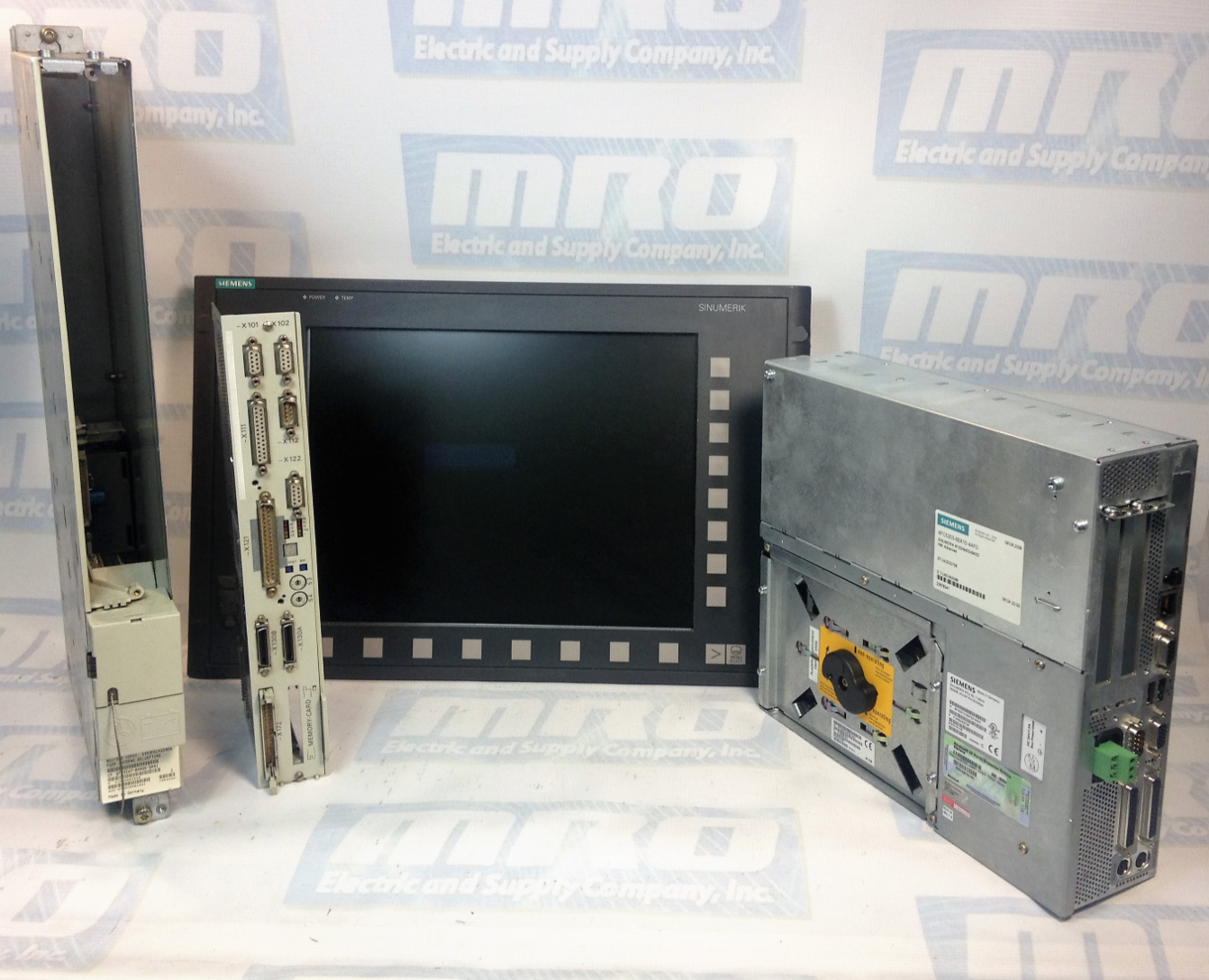
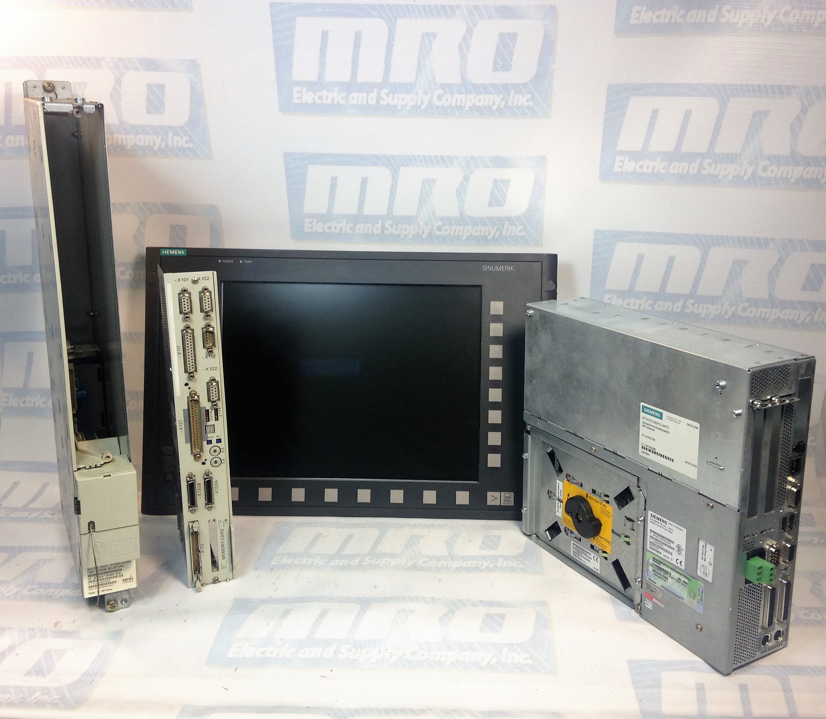
The Siemens SINUMERIK 840D sl is a popular open CNC for modular and premium machining concepts with powerful and dynamic system functions that can be used for a wide range of applications. The CNC system is drive based, and can handle up to 93 axes or spindles and any number of PLC axes. The 840D sl can be used in combination with SINAMICS S120 drives and SIMATIC S7-300 PLCs. The system’s powerful hardware architecture and intelligent control systems ensure machining with the highest level of performance and precision. Additionally, there are a number of solutions that allow for easy IT integration.

The SINUMERIK 840D sl can be used for a wide range of applications including:

  • Turning
  • Milling
  • Gear Machining
  • Grinding
  • Machining Composites
  • Handles and CNC Machining using Robots
  • Nibbling, Waterjet Cutting, Laser Machining, & Plasma Machining
  • Multitasking

The SINUMERIK 840D sl has extremely high precision and performance with accuracy up to 80-bits nano. Its dynamic feed forward control ensures that following error is completely compensated for. With its superb algorithms such as Look Ahead, this system can perform at maximum speed with the same level of performance. The SINUMERIK system also minimizes idle time to keep your production levels at maximum capacity. It can handle kinematic transformations with ease, and sets the standard in energy efficiency. The SINUMERIK 840D sl has a number of integrated safety functions to protect personnel and other machines.

Below is the Siemens SINUMERIK Alarm List:

400000PLC STOP %1 Definitions: PLC not in cyclic mode. Travel with the machine is not possible. %1: 1 Ready(User program has not been started) 2 Break (User program has been interrupted) 3 Error (Other PLC alarm with PLC Stop active) Reaction: Alarm display. Remedy: Rectify other PLC alarm; Switch on menu in PLC stop position or test user program. Program Continuation: Alarm display showing cause of alarm disappears. No further operator action necessary.
400001System error %2 Definitions: %1 :Type number With this alarm, internal alarm states are displayed that, in conjunction with the transferred error number, provide information on the cause and location of the error. Reaction: PLC Stop Remedy: Notify Siemens of this error together with the error message. Program Continuation: Switch control OFF – ON.
400002System error %1 Definitions: %1 :Type number Internal error states are displayed with this alarm. An error number is also specified to provide further details about the cause and location of the error. Reaction: PLC Stop Remedy: Report this error to Siemens along with the type number. Program Continuation: Switch control OFF – ON.
400003Faulty connection to the operator panel Definitions: %1 :Type number This alarm displays that the connection to the machine control panel via the MCPA module has been interrupted. Reaction: Mode group not ready for operation Remedy: Check connection to the MCPA module. Program Continuation: Clear alarm with the Delete key or NC START.
400004Code error: %2 network %1 Definitions: %1 :Network number %2 :Internal error code, module type The user program contains an operation which is not supported by the control. Reaction: PLC Stop Remedy: Modify and reload user program. Program Continuation: Switch control OFF – ON.
400006Loss of remanent PLC data Definitions: The following causes are possible: Control handling (e.g. standard PLC deletion, power up with default values) Control handling of power up with backed up data without backing up data in advance Support time exceeded Reaction: Alarm display. Remedy: Update the data required. Program Continuation: Clear alarm with the Delete key or NC START.
400007Operand error: %2 network %1 Definitions: %1 :Network number %2 :Module type Reaction: PLC Stop Remedy: The variable displayed must be checked in the user program for violation of the address range, impermissible data type and alignment errors. Program Continuation: Switch control OFF – ON.
400008Programming tool – version is not compatible %1 %2 Definitions: %1 :Programming tool version This version is not compatible with the product version of the control system. Reaction: PLC Stop Remedy: Translate the user program using a suitable programming tool version and load in the control. Program Continuation: Switch control OFF – ON.
400009Computing time overrun at PLC level: %2 network %1 Definitions: %1 :Network number %2 :Module type Check user program of the corresponding network displayed. Reaction: PLC Stop Remedy: Change user program Program Continuation: Switch control OFF – ON.
400010Arithmetic error in user program: Type %2 network %1 Definitions: Check user program in the specified network. %1Network number, module ID %2 = 1:Division by zero using fixed-point arithmetic 2:Floating-point arithmetic Reaction: PLC Stop Remedy: Change user program. Program Continuation: Switch control OFF – ON.
400011Maximum number of subroutine levels exceeded: %2 network %1 Definitions: %1Network number %2Module ID Check user program in the specified network. Reaction: PLC Stop Remedy: Change user program. Program Continuation: Switch control OFF – ON.
400013PLC user program is incorrect Definitions: The PLC user program in the control is incorrect or is not available. Reaction: PLC Stop Remedy: Reload PLC user program. Program Continuation: Switch control OFF – ON.
400014PROFIBUS DP: power up interrupted, type: %1 Definitions: %1: 1PROFIBUS DP power up interrupted 2Software versions of NC and PLC do not match 3Number of slots per function exceeded 4PROFIBUS DP server not ready Reaction: PLC Stop Remedy: Types 1 to 3:Report error to Siemens Type 4:802D sl – Check and/or replace PCU hardware and/or check MD 11240 Program Continuation: Switch control OFF – ON.
400015PROFIBUS DP: I/O defect: log adr. %1 bus/station: %2 Definitions: The PLC-AWP is using I/O addresses which are not available. %1Logical I/O address %2Bus number/station number Causes of error: Bus peripheral has no voltage Bus address set incorrectly Bus connection faulty Active MD 11240 (SDB configuration) is set incorrectly Reaction: PLC Stop Remedy: Rectify the error using the error cause Program Continuation: Switch control OFF – ON.

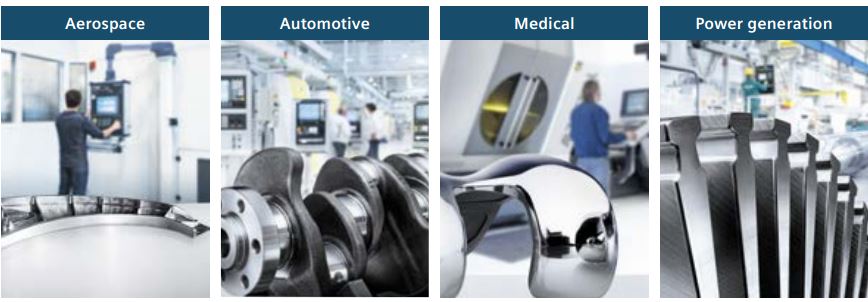
The SINUMERIK 840D sl can be used in many different industries. Its customization solutions allow it to fulfill the requirements of even highly regulated industries. There are even support services and solutions provided for specific niches.
SINUMERIK 840D SL Applicatons

MRO Electric offers a variety of support services for the SINUMERIK 840D sl. These include providing new spares, refurbished components, and repair services. If you are in need of a replacement part or FANUC repairs, please call us at 800-691-8511 or email sales@mroelectric.com.
6SN1123-1AA00-0CA2

Siemens 6SN1123-1AA00-0CA2: Beyond the User Manual

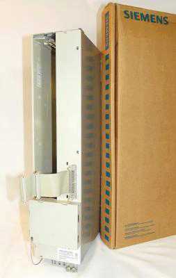
The Siemens 6SN1123-1AA00-0CA2 is a Simodrive 611, 1 Axis Power Module. With the control module, the 6SN1123-1AA00-0CA2 forms the drive module for feed or main spindle applications. The module provides power to the control boards as well as the connected motors. It can be used to operate a variety of Siemens and 3rd party motors. This module is graded according to a certain rating and can be supplied with three different cooling techniques. The module is equipped with overload protection. When this is dimensioned properly,  it prevents both the cables and motors from being overloaded. the power module has two operating modes – one for Feed drives and another for Main spindle drives.

The 6SN1123-1AA00-0CA2 can be used for a variety of solutions due to its modular and space saving attributes. The module’s output limits can be modified by the control module in use. The drive modules can be operated from both an unregulated and regulated supply modules belonging to the Simodrive 611 drive system. The power module draws its supply required to control the motors from the DC link.

Then installing a control board into the 6SN1123-1AA00-0CA2, make sure the following is observed:

  1. Ensure that the power module is in a no-voltage condition.
  2. Check that the memory module is inserted and locked into place in the control board.
  3. Insert the control board into the power module.
  4. Tighten the screws retaining the board (2 on front panel).
  5. Connect the front panel of the board corresponding with its applicable connection diagram. The mating connectors must be inserted at the appropriate interface.
MRO Electric stocks both new and refurbished 6SN1123-1AA00-0CA2 Power Modules. For more information or to request a quote, please call 800-691-6511 or email sales@mroelectric.com.

6SN1123-1AA00-0CA2
6SN1123-1AA00-0CA2