In industrial automation, the Human-Machine Interface (HMI) is the critical bridge between operators and complex machinery. It’s the window into processes, the tool for issuing commands, and the first line of defense for diagnostics. Choosing the right HMI is paramount for efficiency, reliability, and safety.
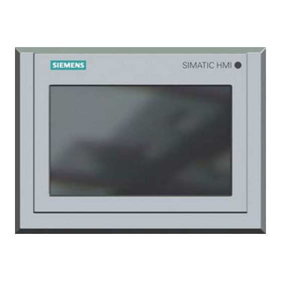
The Siemens TP700 line (like the 6AV2124-0GC01-0AX0), stand out as a premier choice for demanding applications. The TP700 Comfort Panel is a 7-inch touchscreen device that embodies a perfect blend of powerful performance, stunning visualization, and rugged industrial design. Let’s explore the key features that make it an indispensable tool for modern automation.
At the heart of the TP700 is a 7-inch widescreen TFT display with a resolution of 800 x 480 pixels (WVGA). Its screen consist of 16.7 million. The display supports true color depth, allowing for incredibly detailed and nuanced graphics. The use of photo-realistic images and smooth gradients make system status intuitive to understand at a glance.
Additionally, the modern widescreen aspect ratio provides more horizontal space for organizing controls, trends, and alarm displays. This reduces the need for navigation and keeping more critical information visible simultaneously.
Connectivity
The TP700 is programmed seamlessly within Siemens’ Totally Integrated Automation (TIA) Portal engineering framework. This unified environment allows for effortless integration and significantly reduces configuration time. The TP700 also comes with a built-in 2-port PROFINET switch. This enables simple daisy-chaining to other devices like PLCs or drives without the need for external switches. The result is easier cabinet wiring. Additionally, it supports other industrial protocols, including PROFIBUS, Modbus, and OPC UA. This makes the TP700 versatile for connecting to a vast ecosystem of third-party devices and IT systems.
Enhanced Security and Data Logging
The TP700 supports extensive user management with various permission levels. Users can control which operators have access to specific functions, parameters, or screens. This ensures security and preventing unauthorized changes. The panel can also store and process data directly on its internal memory or to an external SD card. This is essential for batch processes, quality tracking, and historical analysis for diagnostics and optimization.
Who is the TP700 Comfort Panel For?
The Siemens TP700 is the ideal solution for a wide range of mid-to-high-end applications across all industries. One of the first uses that come to mind is machine building. The TP700 brings a high level of control for machines perform tasks like assembling, injection molding, or complex packaging. Another industry that benefits from TP700 is the treatment and processing industry. Think water and waste treatment or chemical processing. The automotive industry is also another obvious choice as the TP700 gives the operator precision access to the assembly robots.
Conclusion
The Siemens TP700 Comfort Panel is more than just an interface; it’s a strategic investment in operational intelligence. By combining a brilliant display, powerful processing, rugged construction, and seamless integration within the TIA Portal, it empowers operators, simplifies processes, and provides the reliability required for 24/7 industrial operation. For engineers and system integrators looking to build advanced, efficient, and future-proof control systems, the TP700 Comfort Panel represents a benchmark in HMI technology.
Looking For a TP700
Are you in the market for a TP700, either new or refurbished? Reach our team of experts and let them help you get your operation running.
Industrial automation facilities rely heavily on Industrial Control Systems (ICS) to manage production lines, robotic systems, and machinery. Key components such as Programmable Logic Controllers (PLCs), Human-Machine Interfaces (HMIs), and motor drives are essential for operational efficiency. However, as these systems become more interconnected, they face growing cybersecurity risks that can lead to production downtime, safety hazards, and financial losses.
This article explores why securing ICS infrastructure is critical in automation facilities and how manufacturers implement protective protocols to safeguard their control systems.
Why ICS Security is Critical in Automation Facilities
The importance of ICS security in industrial automation goes beyond just simply protecting company assets. It also ensures employee safety and making sure production runs with minimal disruptions.
Protecting Intellectual Property & Supply Chains
Cyber espionage can steal trade secrets, affecting competitive advantage. A breach in one facility can cascade across the supply chain, delaying deliveries for automotive, pharmaceutical, and electronics industries. Having ICS security monitors and protects from any attacks or leaks of intellectual property.
Key Threats to ICS in Automation Facilities
Listed below are common threats that automation facilities face and their impacts. They highlight the crucial nature of ICS.
Gains access to engineering workstations controlling drives.
Insider Threats
Employees or contractors misuse access to modify PLC logic.
Unsecured Remote Access
Hackers exploit VPNs or default passwords to take over HMIs.
Supply Chain Attacks
Compromised firmware updates infect PLCs and drives.
Protocols for Securing ICS in Automation
Every company should systems and protocols in place to be able to respond quickly and effectively to attempts at breaches. Here are some suggested protocols that would help ensure optimal ICS security.
Network Segmentation
By separating OT networks from IT systems, you limit attack points from the outside. Be sure to use industrial firewalls to filter traffic between PLCs, HMIs, and drives.
Securing Access Controls
By limiting security access to only the most vital roles, not only do you have control over access but also an easier way to determine where security vulnerabilities are. Security tools such as Role-based access control designates levels of access to an individual based on the role assigned to them. Likewise, multi-factor authentication limits remote accessibility for specific instruments like HMI’s to individuals with specific clearance. You can also assign temporary credentials for individuals who need specific access for a specific amount of time.
Security Patches and Firmware
Cybersecurity is a consistently evolving challenge that requires companies to have the most updated security features. This is often done through security firmware in the form of patches and updates. Having the most recent update to your firmware is crucial to making sure your system doesn’t fall victim to an unknown advanced virus or backdoor software.
VPN Encryption
Using a VPN encrypts the IP addresses of your PLC’s making it nearly impossible for a bad actor to gain remote access to them.
Conclusion
Securing ICS infrastructure in automation facilities is not optional—it’s a necessity to prevent operational disruptions, safety risks, and financial losses. By adopting protective protocols such as network segmentation, access controls, and real-time monitoring, manufacturers can defend their PLCs, HMIs, and drives from evolving cyber threats.
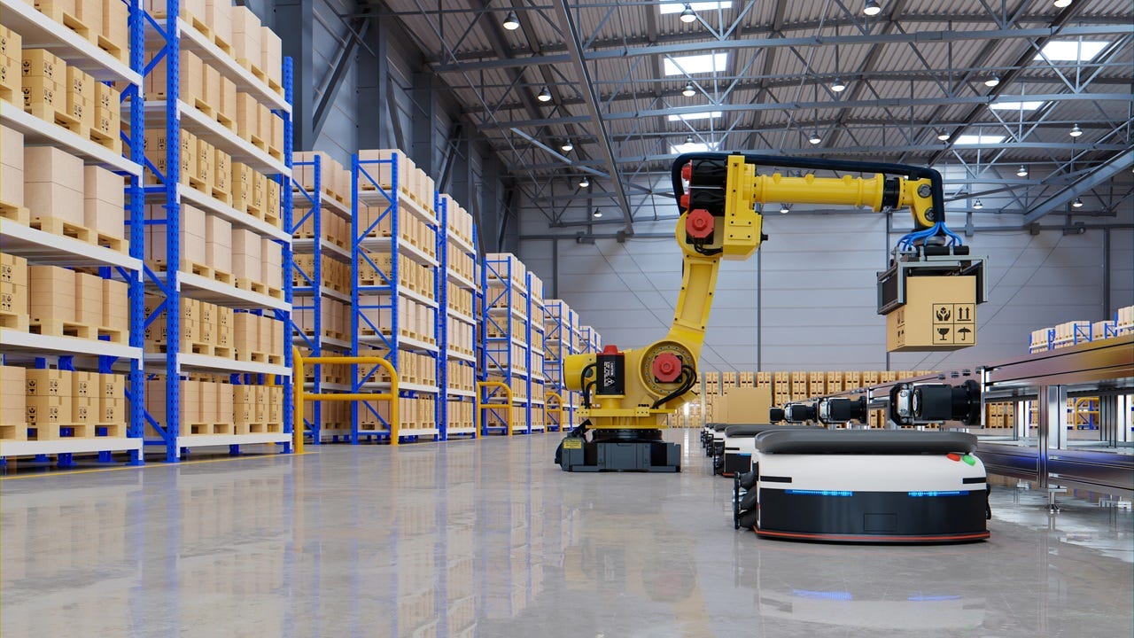
The modern landscape of industrialization is a chaotic mix of unnatural speed, precise accuracy, and unprecedented efficiency. This in large is thanks to the development of Automated Material Handling (AMH). AMH has emerged as a game-changing technology that optimizes the movement, storage, and control of materials within manufacturing, warehousing, and distribution environments. By leveraging robotics, artificial intelligence (AI), and advanced software systems. AMH reduces human intervention, minimizes errors, and enhances productivity.
What is AMH?
In short, AMH refers to the use of computerized and robotic systems to transport, store, and retrieve materials with minimal human involvement. Some examples of these systems include, conveyor systems for fast and efficient transport of materials across warehouses. Self-navigating robots/vehicles that can move materials around autonomous. These robots can also be paired with advanced storage systems to me retrieval a more streamlined process. Additionally robotic arms can quickly and safely pick up items that would normally be too heavy for one person to life. Robotic arms also serve a crucial role in automated assembly.
The Importance of AMH
Automated Material Handling is a relatively new system that would make it easy to dismiss. However, in the short time it’s been around, it has made its role in automation absolutely crucial in keeping up with demand. On average, businesses that integrate AMH see about a 7.9% uptick in their annual growth. Of course speed is not the only factor that plays into this growth. Automating material handling reduces labor cost and increases efficiency with less margins of error.
While the initial cost of Automated Material Handling is undeniably high, the reduced labor, saving of space, and higher accuracy count makes it a great long term return on investment (ROI).
On a more technological level, AMH is designed to be scalable and upgradable integrating newer technologies such as AI. As a business grows, the operational space and systems are easily expandable to match that the pace and demands of that business. Likewise, AI-driven analytics ensure live tracking of inventory and orders.
Who Benefits from AMH
When we talk about industries that benefit most from automated material handling, manufacturing and retail tend to be at the forefront of what everyone thinks. AMH speeds up the manufacturing process in times that would take a team much longer to do. At the same time, the retail world utilizes AMH for rapid order fulfillment and warehouse distribution.
However, the pharmaceutical industry also utilizes AMH for handling hazardous materials and other substances. At the same time the food and beverage industry uses automated machine handling to keep their products at safe and preferable temperatures.
Conclusion
Automated Material Handling is no longer a luxury but a necessity for industries aiming to boost efficiency, cut costs, and stay competitive. By integrating AMH solutions, businesses can achieve faster operations, higher accuracy, and a safer work environment—paving the way for a smarter, more automated future.
Need Equipment?
Are you looking to get your automated? Perhaps you already are automated but need to get some parts replaced? Reach out to our team of experts to help connect you with the right equipment to get your operation up and running!
Circuit breakers are essential safety devices in any electrical system, protecting your home or workplace from overloading. Over time, they can wear out or malfunction, so it’s important to test them periodically to ensure they’re working correctly. In this guide, we’ll walk you through how to safely test a breaker.
There are different reasons to test circuit breakers. Where testing is most important, is in the area of safety. Regular testing of circuit breakers maintains safe electrical systems by preventing things like power surges which can damage equipment. Equipment isn’t the only safety concern that prompts regular breaker testing. Routine testing of circuit breakers can prevent fires from occurring.
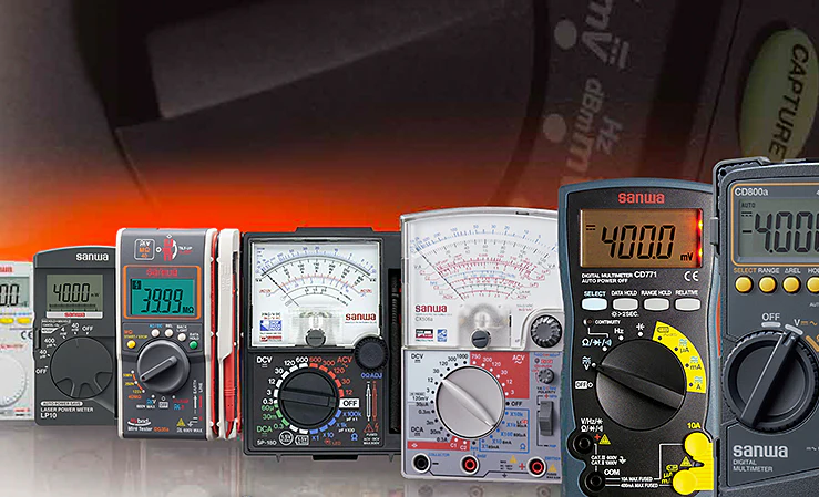
Tools For Testing
When testing breakers, several tools are vital for conducting test. Among them, the tools most important are insulated gloves and a multi-meter. The insulated gloves are critical in safeguarding you from potential electrical hazards, and the multi-meter is important in circuit breaker diagnostics.
The next step would be to visually scan for any signs of anything being off. That usually looks like burn marks, corrosion, or a tripped breaker. Any breaker that appear damaged should be replaced immediately. With your multimeter set to Voltage, test the breakers and circuits. A normal reading should show 120V for standard home circuits and 240V for larger circuits. A reading of 0 indicates a faulty breaker.
Perform a manual check by switching the breaker to the “ON’ position and then press the “TEST” button, the circuit should trip immediately. After tripping the breaker reset it back into the “ON” position, if it does not reset, then the breaker will need replacing.
If the breaker consistently fails voltage test, or trips without an obvious cause, call a professional electrician.
Conclusion
Testing a breaker is a simple but crucial maintenance task. By following these steps, you can ensure your electrical system remains safe and functional. If you’re unsure or encounter issues, always consult a licensed electrician for professional help.
Dirty Power
One of the biggest contributors to bad circuit breakers is what is commonly known as “dirty power”. More information about dirty power and how to prevent it can be found here.
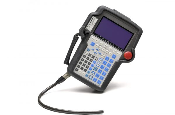
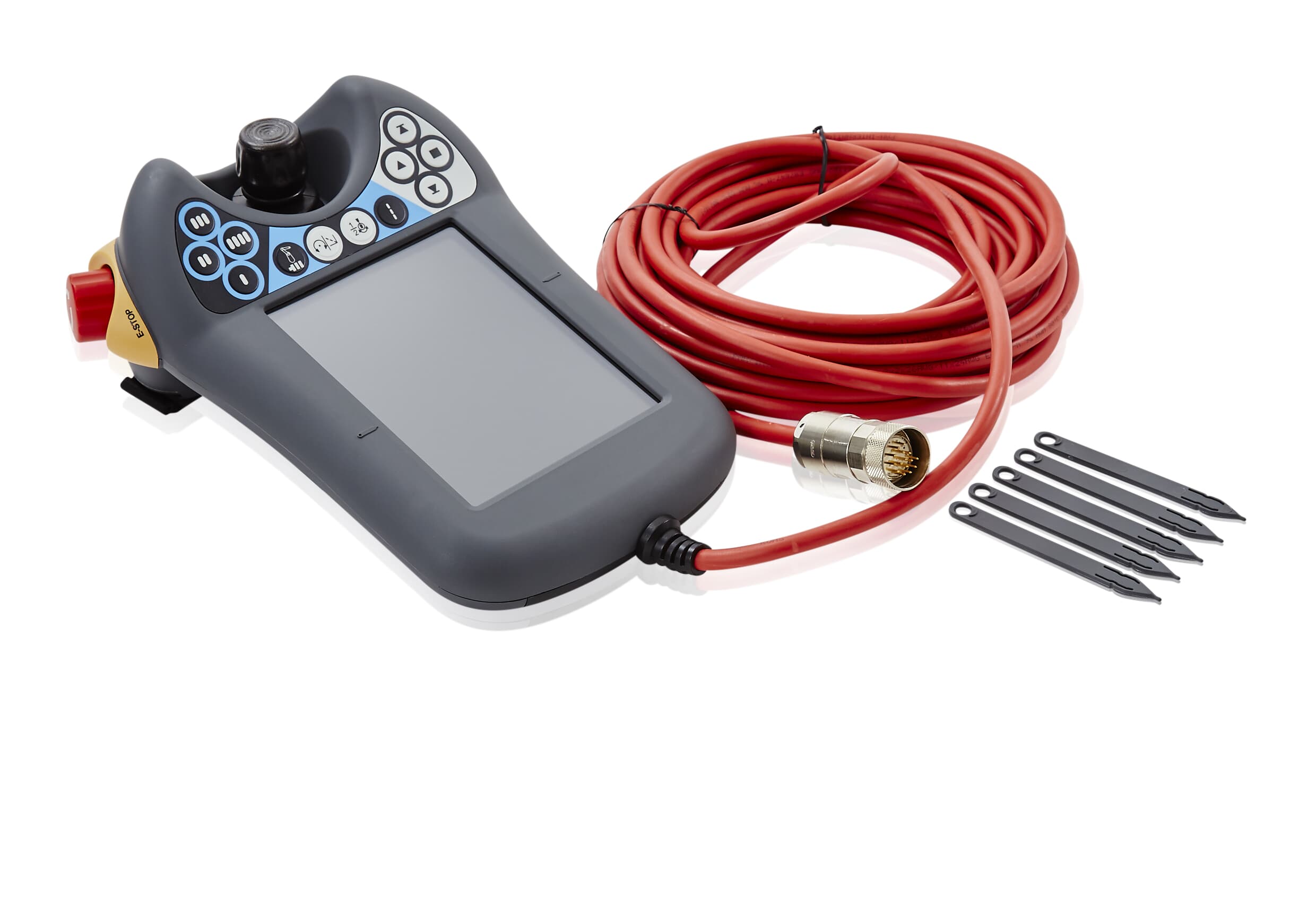
Through industrial automation, manufacturing has come a long way. The leaps and bounds in speed, precision, safety, and overall efficiency has vastly improved from earlier industrial age. One of the attributions to this success easily goes to the teach pendant. The invention of this handheld controller has allowed operators to program and troubleshoot a lot of problems with ease. In this article, we explore the role of teach pendants in automation, their key features, and their impact on modern manufacturing.
A teach pendant is a handheld control terminal used to program and operate industrial robots. It typically consists of a display screen, buttons, joysticks, and emergency stop functions. Operators use teach pendants to manually guide robots through tasks, define movement paths, set parameters, and store instructions for automated operations. This process is where teach pendant derives its name from.
Key Functions of a Teach Pendant
Teach pendants offer a multitude of functions making it possible for them to complete variety of tasks. Here are some examples of the function of teach pendants.
Teach pendants allow for easy creation and editing of robotic programs. Waypoint and motion sequences can be recorded for repetitive task such as welding and assembly.
Operators can have precise control over equipment movements via joystick or directional buttons.
Teach pendants provide real-time feedback, error messages, and system status updates to quickly diagnose issues.
Emergency stop buttons and dead-man switches ensure safe operation by halting robot movement instantaneously.
Operators can fine-tune speed, torque, and trajectory settings to optimize performance.
Advantages of a Teach Pendant
Teach pendants bring with them a lot of advantages that generally do not come with traditional control systems. For starters, teach pendants are made to be easily user-friendly and intuitive making it easy to train someone on. There’s a level a flexibility that they offer when it comes to programming and changing production settings. An operator can adjust between high and low volume production outputs.
Teach Pendant Types
Wired Teach Pendants – Connected directly to the robot controller, ensuring reliable communication.
Wireless Teach Pendants – Offer greater mobility but may have latency or interference concerns.
Brand-Specific Pendants – Companies like FANUC, ABB, KUKA, and Yaskawa design proprietary pendants tailored to their robots.
Conclusion
Teach pendants remain indispensable in industrial automation, bridging the gap between human operators and robotic systems. As technology advances, these devices will continue to enhance productivity, safety, and adaptability in smart factories worldwide.
By understanding their functionality and benefits, manufacturers can maximize the potential of robotic automation and stay competitive in an increasingly automated industry.
In Need of a Teach Pendant
With a large selection of FANUC, ABB, and KUKA teach pendants, we should have controller that fits your operating needs. Reach out to our team of experts and let us help you optimize your automation experience.
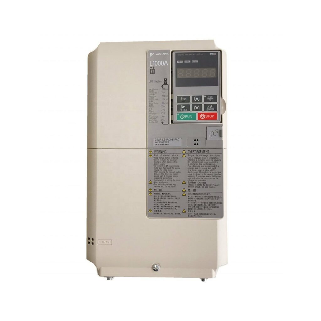
AC drives, also known as variable frequency drives (VFDs) or adjustable speed drives (ASDs), are essential components in modern industrial and commercial applications. They control the speed and torque of AC motors by varying the frequency and voltage of the power supplied to the motor. This capability enhances energy efficiency, reduces mechanical stress, and improves process control.
In this article, we will explore what AC drives are, their key components, how they work, and their benefits in various applications.
In short, an AC drive is an electronic device that regulates the speed and performance of an alternating current (AC) motor. Unlike traditional fixed-speed motors, AC drives allow for precise control over motor speed, acceleration, and deceleration, making them ideal for applications where varying speeds are necessary.
To better understand an AC Drive, we need to think about it in terms of “what makes up an AC Drive” and “How it works”.
The key components of an AC Drive consist of a Rectifier, that converts AC supply to DC voltage. Capacitors that filter and stabilize DC voltage. An inverter that uses pulse-width modulation (PWM) to recreate an AC waveform. Adjustable output controls like a variable switch. This controls AC output and motor speeds.
You can read ore detailed information about AC drives here.
What are the Benefits of AC Drives?
While the upfront cost of installing an AC drive seems high, benefit of long terms savings make investing in an AC drive, a no brainer. Long term savings stands as the biggest benefit of having an AC drive. AC drives manage power consumption of your overall operation making sure your machines are using only the base load requirements. This improved regulation of energy also means less mechanical and electronic stress on your equipment resulting in increased longevity of your machine. The diminished stress also means less maintenance needed which translates to more savings!
Common Applications
AC drives do a lot of behind-the-scenes task that many do not really recognize. However, when you realize how many industries rely on automation, the importance that AC drives have becomes very apparent. Some obvious ones like manufacturing and energy where AC drives get used to run machines like conveyor belts or wind turbines. Some lesser known applications could include water treatment where AC drives an be used to control pumps. AC drives are also used in HVAC systems to control fans, pumps, and compressors for better energy efficiency.
Conclusion
AC drives play a crucial role in modern motor control systems, offering energy efficiency, precise speed regulation, and improved operational performance. By understanding how they work and their benefits, industries can optimize their processes, reduce costs, and enhance equipment longevity.
Whether in manufacturing, HVAC, or renewable energy, AC drives continue to revolutionize motor control, making them indispensable in today’s automated world.
In Need of an AC Drive?
Are you in need of replacing or getting a new AC drive? Let our team of experts help you find a product right for you. Reach out to us and let us help you get your operation up and running!
Some sports fans take a loss in stride, while others…not so much. Whether it’s blaming the refs, talking trash even after the final whistle, or full-blown meltdowns, certain states’ sports fans just feel a defeat more deeply. With high-stakes games and bracket-busting upsets fueling emotions this time of year, the intensity is at an all-time high.
To find out which states have the sorest losers, we surveyed over 2,100 sports fans nationwide, asking them about the sportsmanship—and not-so-sportsmanlike reactions—of fans in their state. The results reveal which states take losses way harder than others.
States Most & Least Likely to Be Sore Losers
We surveyed sports fans across 44 U.S. states, asking 10 questions to gauge their level of sportsmanship, competitiveness, and just how hard they take a big loss. The survey measured everything from trash-talking habits to how often fans blame the refs, whether they’ve been called a sore loser, and even how frequently fights break out during games. Each question was answered on a 1-to-5 scale, with 5 indicating a higher likelihood of sore loser behavior. We then averaged the responses and indexed them into a final sore loser score out of 100 for each state—with higher final scores signaling states where taking an “L” hits the hardest.
These are the five states with the sorest losers, and their respective sore loser scores (out of 100):
Alabama – 93.4
Pennsylvania – 84.1
Massachusetts – 68.1
New Jersey – 67.7
West Virginia – 66.5
When it comes to taking a loss very personally, no one does it quite like Alabama.Topping the list with asore loser score of 93.4, Alabama sports fans bring an unmatched level of passion to every matchup. And when the scoreboard doesn’t go their way? Let’s just say they feel it. More than half of Alabamians (51%) admit to having a total meltdown after a big loss—the only state in the survey where this was the most common reaction. And if you’ve ever heard “the refs blew it!” echoing through an Alabama bar or living room, that checks out too: 33% say they “almost always” blame losses on bad calls, while 41% say they do it “often.” What’s more, 43% of Alabama respondents say they’ve witnessed a sports fan throw a tantrum after a loss more times than they can count.
That intensity isn’t just reserved for college rivalries—it starts early. Alabama parents bring just as much energy to the sidelines of youth sports. A quarter of Alabama respondents (25%) say parents in their state “almost always” get too worked up at kids’ sporting events, while 37% admit they do so “often.” Whether it’s a Saturday in Bryant-Denny or a little league game in Birmingham, one thing is clear: Alabama takes its sports very seriously.
Trailing behind but still bringing the drama are Pennsylvania, Massachusetts, New Jersey, and West Virginia—all states where sports are treated with near-religious devotion. When asked, “Which best describes your state’s sports fanbase?” Pennsylvania respondents were the most likely to choose “We talk trash before and after the game, win or lose”—a sentiment shared by nearly 60% of them. And that competitive spirit doesn’t always go unnoticed. Half of Pennsylvania respondents admit they’ve been called a sore loser at least once or twice, while in neighboring New Jersey, 45% of respondents say the same.
Over in Massachusetts, nearly half of respondents say sports are taken “extremely seriously—every game feels like a big deal.” But if you’re looking for high-intensity matchups, West Virginia might take the crown. More than half (54%) of respondents in the state have witnessed a fight break out during a game they were playing in. And the passion starts early—15% of West Virginia respondents say parents in their state “almost always” get too worked up at kids’ sporting events, while 38% say it happens “often.”
On the opposite end of the spectrum, these are the five states least likely to be sore losers, and their respective sore loser scores (out of 100):
Oregon – 11.8
Idaho – 16.5
Arizona – 24.7
Maine – 30.8
Minnesota – 31.6
Some states accept losses with a bit more grace than others. According to survey results, Oregon is the least likely state to be full of sore losers, with a sore loser score of just 11.8. And the numbers back it up: 56% of Oregonians have never been called a sore loser, and when their team takes a big loss, 67% say they’re unbothered or don’t care at all, simply shrugging it off with an “it’s just a game” mentality. Even trash talk is kept to a minimum—a third (33%) rarely or never talk smack after a loss. And if you’re looking for sports parents who keep their cool, Oregon is the place to be. Not a single respondent said parents in their state “almost always” get too worked up at kids’ sporting events, and only 13% said it happens “often.”
Arizona and Idaho also rank among the least sore loser-prone states, with nearly half of respondents (48% in AZ, 47% in ID) saying they’ve never been called a sore loser. Idaho, in particular, leads the nation in sportsmanship—32% say they’ve never seen a fan throw a tantrum after a loss, the highest percentage of any state. Meanwhile, over in Maine, 64% of respondents say sports fans there don’t dwell on losses, and in Minnesota, 63% describe their fanbase as “passionate but mostly respectful.” Minnesotans also keep their cool in the heat of the game—67% say fights during games almost never break out, while another 20% say it’s rare.
Full State-by-State Ranking
Curious about where your state ranks? Our interactive table below breaks down the full survey results, showing the most common answers for all 10 sore loser-focused questions in each state. You can search for your state or sort by different categories to see which fanbases take losses the hardest—and which ones truly let it go.
Closing Thoughts
At the end of the day, some states take sports losses harder than others—and our survey proves it. Alabama, Pennsylvania, and Massachusetts top the list as the sorest losers, where fans are more likely to blame the refs, talk trash after a loss, and even witness full-blown meltdowns. Meanwhile, Oregon, Idaho, and Arizona keep things cool, proving that not every fanbase lets a tough defeat ruin their day. Whether your state lives for the thrill of competition or takes an “it’s just a game” approach, one thing is clear: sports bring out strong emotions, win or lose.
Just like sports fans rely on their teams to show up and perform, businesses rely on industrial automation systems to keep things running smoothly—because downtime is never an option. At MRO Electric, we specialize in repairing and supplying industrial automation components, helping businesses maintain peak performance even under pressure. Get in touch with us today to keep your operations running at championship level.
Methodology
To find the states with the sorest losers, we conducted a survey of 2,196 U.S. sports fans across 44 states. The survey ran over a one-week period, from February 12 to February 19, 2025. Alaska, Montana, North Dakota, South Dakota, Vermont, and Wyoming were excluded from the survey due to limited survey respondents in those states.
For the state ranking portion of our study, we evaluated states across 10 key survey questions that reflect sore loser behaviors, ultimately measuring how sports fans in each state react after a big loss. Questions included their level of trash talk, tendency to blame referees, frequency of being called sore losers, and how often they witness fights during games, among others. Each question was answered on a 1-to-5 scale, with 5 indicating a higher likelihood of sore loser behavior. We then averaged the responses and indexed them into a final sore loser score out of 100 for each state—with higher final scores signaling states most likely to be sore losers.