The encoder system is connected to the SINAMICS S120 via DRIVE-CLiQ. Motors with DRIVE-CLiQ interfaces are designed for this purpose. These motors simplify commissioning and diagnostics because the motor and encoder type are identified automatically. The Sensor Modules(SME20, SME25, SME120, and SME125) are only to be used with machines and may ONLY be connected to the DRIVE-CLiQ interfaces of proprietary components. Direct encoder systems outside the cabinet can be connected to the Sensor Modules External. The SMEs evaluate these encoder systems and convert the calculated values to DRIVE-CLiQ. No motor or encoder data is stored in the Siemens SMEs. The Sensor Modules External provides the encoder power supply. The power supply for the SME is provided from the connected DRIVE-CLiQ cable. This should be taken into consideration when selecting the DRIVE-CLiQ cable. SMEs have a higher degree of protection(IP67) which means it is suitable to be installed on the outside of the cabinet.
Part numbers for the SMEs include:
- SME20 – 6SL3055-0AA00-5EA3
- SME25 – 6SL3055-0AA00-5HA3
- SME120 – 6SL3055-0AA00-5JA3
- SME125 – 6SL3055-0AA00-5KA3
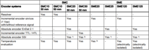
Below is a chart that shows the connectable encoder systems between the SMC and SME modules.
Does your Siemens SINAMICS S120 series encoding module need to be serviced? As with all of our services, our repairs come with a 12 month guarantee. Our repair service is based on doing the right job, and getting your part back to you as soon as possible. Every part we refurbish is tested to make sure they work the way they are supposed to. Our factory-trained technicians have many years working with Siemens products. Minimize your future downtime today by contacting MRO Electric and Supply right now.