Being a leader of the robotics industry for over 50 years, Kawasaki has developed one of the most complete lines of e-controllers on the market. All of these controllers are suited with a wide array of features including:
- High powered CPU performence
- Large, easy to use LCD Display
- Optimized key layout
- Easily accessible safety switches
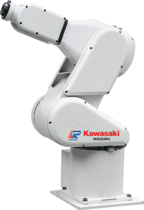
The E76/77 family of controllers are very compact and used for smaller robot arms. One of these arms are the RS003N Robot, which has a maximum payload of 3kg and has horizontal and vertical reaches of 620mm and 967mm, respectively. The controllers with these robots specialize in assembly and material handling applications.
The E9 family of robotic teach pedants are also built very compact, however these devices are typically used in medium-duty applications. Unlike the other two families of controllers, the E9 family features an open structure system with a direct cooling system. However, like the E7 and E3 families, the enclosed structure with indirect cooling is an available option. The E9 family takes full advantage of the digital servo drive powering it to have a maximum payload capacity of 40kg.
E30/32/33/34 controllers at their base are very alike the E76/77 controllers but with more power. These devices are not as compact as the previous devices we have discussed, however the reason being they are highly expandable and are easier to maintain. Features such as Kawasaki’s K-Logic sequencer software allow the addition of up to 16 total controllable axes. The E3 family of Kawasaki e-controllers are able to handle the following maximum payloads:
- E30 – 145 kg
- E32 – 180 kg
- E33 – 195 kg
- E34 – 180 kg
If you are interested in learning how to purchase the robot arm, the controller, or any other part/device that goes into an industrial robotic set-up, please call MRO Electric and Supply at (800)691-8511 or email us at sales@mroelectric.com and we will help you get what you need.