Low-Code and the Future of PLC Programming

Low-code programming is an emerging trend promising to revolutionize software applications’ development and deployment. Utilizing visual modeling tools and pre-built components, low-code programming helps developers create and customize applications quickly and easily, without the need for extensive coding skills. Not only is it shaking up the world of software development, but it is making big splashes in the world of industrial automation. This is especially so when we talk about PLCs.

The Current Language of PLC

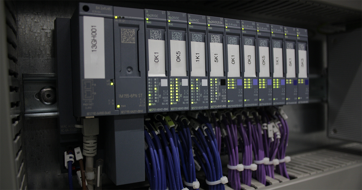
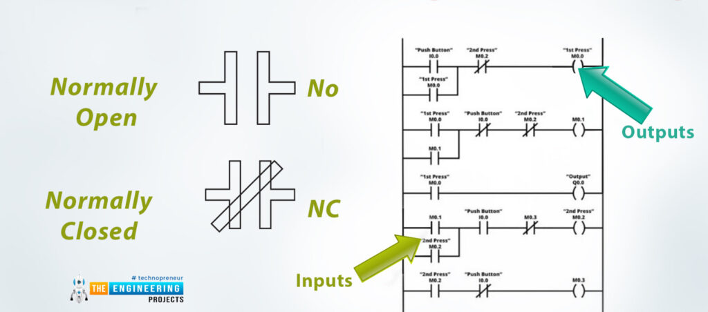
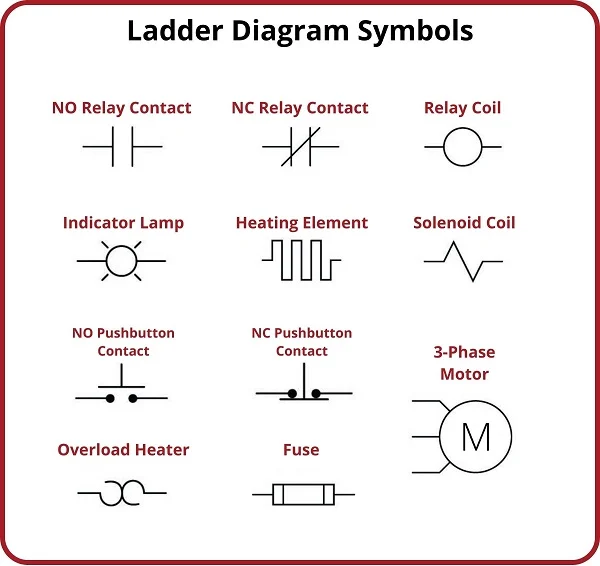
In another blog, we covered ladder logic. This is the primary coding language that PLCs use to function and perform tasks. Ladder logic is based on an older coding language known as C. Traditionally, coding in languages like C requires a mix of prompts formatted in very specific ways. This requires a well-versed coder programming the PLCs. The other challenge is not only that a person has to know the coding language, but also just be able to visualize how it all works together. Lines of code don’t always get along with each other. This sometimes results in an unexpected outcome not seen in the initial programming. This generally gets referred to as a “bug”. A good programmer must be one that can recognize, isolate, and debug what is causing these issues.

What is Low-Code Programming?

Low code is defined as a software development approach that requires little to no coding to build applications and processes. Instead of complex programming languages, it utilizes visual interfaces with basic logic and drag-and-drop capabilities in a development platform. This quick and simple alternative to conventional software development continues to grow in popularity.

Video explaining Low-Code

Applying Low Code to PLC

While the trend of low code exists predominantly in the field of programming and development. It is also a concept being adapted to the field of industrial automation. More specifically, PLCs can adapt the low code model as traditionally they operate on a basic programming language.

The Advantages of Low-Code

There are several advantages to systems using a low-code environment. These advantages include faster times, better productivity, increased flexibility, and reduced costs.

With faster times, developers create applications much faster than traditional coding methods. They use pre-built components and visual modeling tools, to assemble and customize applications without the need for extensive coding.

Faster Times – Low coding allows PLC programmers to input programs much faster and not restricted by traditional coding methods.

Better Productivity – With less effort and time required than traditional programming, facilities can operate faster and more efficiently. An engineer can program a PLC much easier.

Increased flexibility – PLC programmers can quickly debug/modify the program of a PLC a lot easier than finding lines of code and rewriting them when the situation changes.

Low Cost – Low code programming will in the long run be less expensive, as unlike traditional programming, the PLC programmer does not need to have extensive knowledge of coding.


Future Outlook

Ultimately, the outlook for low code’s place in the world of industrial automation appears more prominent than ever. While there are concerns about how it will impact the future labor force. At its core low code serves as another example of automation making a specialized position obsolete. In the end, Low code’s multifaceted advantages of being flexible, quick, and cost-effective make it very appealing to companies across the industry, meaning that (for the time being at least) it’s here to stay.

Updated on March 29, 2023 by Ken Cheng

Common PLC Issues

Common PLC Issues (and how they can be avoided)

PLCs have been crucial for the advancement of industrial automation. Their ability to increase functionality at decreased cost makes them widely used across automated systems. Not only do they have the ability. PLCs are able to give both simple and complex instructions to a variety of systems.

Like any other machine, PLCs are also prone to breaking and having their own issues. An entire PLC cabinet full of devices, blinking lights, and wires can seem intimidating. However, sometimes the issue might be one that can be resolved simply and easily. So before you call a technician to come service your system, here are a few simple troubleshooting you can do that could save your company some time (and money).

Input/Output(I/O) Failure

This is probably the most common failure that affects PLCs. This is usually due to the relationship between the internal and external situations not establishing a connection. This generally gets fixed by finding out what relationship is not being established and isolating the issue.

Signal Interference

This occurs when there is either electromagnetic interference (EMI) or radio frequency interference (RFI). EMI occurs when a PLC is very close to a large motor or any device that creates an electromagnetic field. Lightning striking a device can also cause an EMI issue. ERFI happens when a PLC is next to a transmitting device for a prolonged period of time. Both of these interference will over time degrade the functionality of a PLC. The best thing to do is to position your PLC somewhere far apart from anywhere that can cause either EMI or RFI. If that is not possible, there are also options for protective housings for your PLC.

Memory Corruption

Corrupt memory issues often occur from interference. They also commonly happen when power to the PLC suddenly gets cut off and not properly rebooted. A popular precautionary measure often taken is simpling backing up data to a storage device. A good preventative measure is to not only keep PLCs away from areas of interference but also places with high temperature and humidity.

Power Loss

In industrial automation, machines rely on consistent power to operate. In the event of a sudden power outage (power grid failure, rolling blackouts, etc) it’s generally a good idea to have an alternate or backup power source to rectify the situation should power failure occur.

Communication

A paramount function for PLCs is their ability to communicate with not only one another but also with other equipment like HMIs and drives. Usually, these devices all communicate via Ethernet cable because of their speed and reliability. Ensuring that wires rest properly connected and away from any obstruction or positioned anywhere that might cause them to crimp or get cut, can help prevent a communication error.

Conclusion

In a perfect world, machines run flawlessly 24/7 with no maintenance required. However, in reality, the inevitability of even the most well-kept facility system failing at some point is unavoidable. That being said, following the steps above can help mitigate the wear and tear of your PLC system and get the most life out of them.

Updated on March 22, 2023 by Ken Cheng

A Crash Course on Spindle Motor Fundamentals

The CNC (Computer Numerical Control) spindle motor has been a crucial tool in the world of industrial automation. Its creation has revolutionized the way industrialization functions and has led to increased quality control and productivity overall. The impact of this revolutionary tool in industrial automation is a game changer. With a spindle motor, production can be faster, more efficient, and lower in cost.

The History of CNC

The development of the CNC (Computer Numerical Control) spindle motor is closely linked to the history of CNC technology itself. The first CNC machines were developed in the 1940s and 1950s for the aerospace industry. In the early days of CNC, spindle motors were typically DC motors with brushes. These had limited speed control and were prone to wear and tear. However, as technology advanced, new spindle motors became developed. This included AC motors and brushless DC motors, which offered higher efficiency, greater reliability, and improved speed control. Today, spindle motors are an essential component of CNC machines, driving the tool and controlling the cutting process to achieve high levels of precision and efficiency.

During the 1970s, the development of the CNC (Computer Numerical Control) spindle motor was still in its early stages. According to an article by CNC Masters, spindle motors of the time were typically DC motors with brushes, which offered limited speed control and were prone to wear and tear. Despite these limitations, the introduction of CNC technology represented a significant advance in the machining industry, allowing for greater precision and efficiency. As CNC machines became more widely adopted, the demand for improved spindle motors grew, leading to the development of new types of motors that offered higher efficiency, greater reliability, and improved speed control. Today, spindle motors are a critical component of CNC machines and have come a long way since the early days of the

CNC Advantages

The advantages of CNC spindle motors make them an essential component in modern CNC machines, helping to improve accuracy, productivity, and efficiency in manufacturing operations.

  1. Precision: CNC spindle motors provide high levels of accuracy and precision in machining operations. Lower vibrations also factor into increased accuracy. Fewer vibrations on the bearings and rotor make for a more accurate CNC.
  2. Power: CNC spindle motors can generate high torque. This enables them to handle tough materials and make deep cuts. This is especially important in heavy-duty machining applications, where a lot of material needs quick and efficient removal.
  3. Reliability: Built for durability, CNC spindle motors can withstand the rigors of industrial use. Constructed using high-quality materials, they can operate under high loads and high temperatures.
  4. Low Maintenance: CNC spindle motors are designed with minimal need for lubrication or adjustment. This helps to reduce downtime and maintenance costs, allowing manufacturers to increase productivity and efficiency.
  5. Versatility: CNC spindle motors are available in various sizes and power ratings, making them versatile and suitable for a wide range of machining applications. They can be used with various cutting tools, including drills, end mills, and routers, making them suitable for cutting a range of materials, from metals to plastics.

Spindle Motor Types

CNC Spindle Motors are generally broken down into two types: AC Induction and DC Brushless motors.

With AC induction motors, alternating current generates a magnetic field in the stator windings. This magnetic field then interacts with the rotor and creates torque in the motor drive. AC induction motors tend to be more robust and built tough to meet the demands of industrial applications.

In contrast to AC motors, DC brushless motors use direct current to generate a similar magnetic field in the stator windings. However, a DC motor contains magnets on the rotor that moves to create torque. The advantage of this design is that no friction is being created in the process thereby avoiding a lot of the wear and tear caused by heat and friction. This results in a reliable and long-lasting motor.

An example of a DC Brushed, DC Brushless, and AC Motor construction.

Conclusion

As population and demand increase, the need for CNC will continue to increase with it. Over the years this manufacturing tool has proven its value through its speed, reliability, productivity, and efficiency. This trend will likely be the case for years on end.

Updated on March 17, 2023 by Joe Kaminski

The Future of Ladder Logic

Ladder Logic diagram example by “The Engineering Projects”

What is Ladder Logic?

Ladder Logic is a programming language used in industrial automation and control systems. They specifically are used in Programmable Logic Controllers (PLCs). These specialized computers control industrial machinery and processes.

The History

Richard E. Morley is credited for being the inventor of ladder logic. Morely invented the first Programmable Logic Controller in 1968. Morley’s invention was a significant innovation in industrial control systems, and it paved the way for the development of ladder logic. In the early days of ladder logic, programming involved hand-drawn diagrams on paper. These papers got fed into machines that converted the diagrams into machine code. Over time, ladder logic evolved to include more advanced programming functions.

As a Language

The fundamental building blocks of Ladder Logic are inputs, outputs, and logic gates. Inputs refer to the signals received from sensors or other devices. Outputs refer to the signals sent to actuators or other devices. Logic gates are the basic building blocks of digital circuits and perform logical operations on the inputs to produce the desired output.

Examples of “coils” and “gates”

The diagrams in Ladder Logic consist of horizontal “rungs” that represent the logical operations performed on the inputs, and vertical “rails” that represent the power supply and ground. The rungs stay connected by “contacts” and “coils”. Contacts represent the inputs while coils represent the outputs. Various symbols represent the logic gates. Some examples of these symbols are AND gates, OR gates, and NOT gates. These gates perform logical operations on the inputs.

Ladder Logic’s Advantage

One of the advantages of Ladder Logic is its simplicity and ease of use. The graphical representation of the program makes it easy to understand and maintain. Those with little or no programming experience can quickly learn it. This leads to significant time and cost savings for industrial automation and control systems. Additionally, the standardized symbols and syntax make it easy to share programs between different PLCs and programming software, further reducing development time and costs.

Another advantage of Ladder Logic is its ability to handle complex control functions. Ladder Logic includes advanced programming functions such as timers, counters, and math functions, allowing it to handle complex control functions in industrial processes. This flexibility makes it a powerful programming language for industrial automation and control systems. This is due to customizability to suit specific control requirements.

The Future of Ladder Logic

Ladder Logic is in the development of smarter and more sophisticated industrial control systems. The Internet of Things (IoT) and Industry 4.0 are driving the development of intelligent factories and industrial processes. Ladder Logic can handle the advanced programming functions required for these systems. For example, Ladder Logic can be implemented into program predictive maintenance systems. This system uses sensors and data analysis to predict when equipment will fail and schedule maintenance accordingly.

Another potential future use of Ladder Logic is in the development of more energy-efficient industrial control systems. As sustainability and energy efficiency become increasingly important, Ladder Logic can be used in program systems that optimize energy usage and reduce waste. It can control HVAC systems, lighting systems, and other building automation systems to reduce energy usage and improve efficiency.

The future of ladder logic has been a topic of debate for quite some time. While some are optimistic about it still having a place in the industry, there are others who think that it will eventually go in the way of languages already forgotten. Ladder logic’s story is one that started a long time ago and is continuing to unfold.

Updated on March 7, 2023 by Ken Cheng

Common UNI1405 Fault Codes

Below is a table of common Unidrive faults found within the Control Techniques Unidrive series, more specifically, the UNI1405. MRO Electric offers core credit on exchanges for new and refurbished units, and have a wide selection of option cards such as the UD51, UD73, and UD77. We also repair Unidrives in-house. Contact us if you are interested in finding a new machine so we can keep your downtime to a minimum!

HF81Software Error (odd address word)
HF82Large option module removed
HF83Power Board Code Failure
HF84Current Offset Trim Failure
HF85A to D failure (ES-CC step)
HF86Interrupt Watchdog failure
HF87Internal ROM check error
HF88Watchdog Failure
HF89Unused Interrupts (nmi as source)
HF90Stack Overflow
HF91Stack Underflow
HF92Software Error (undefined op code)
HF93Software Error (protection fault)
HF94Software Error (odd address word)
HF95Software Error (odd address inst.)
HF96Software Error (illegal ext bus)
HF97Level 1 Noise
HF98Interrupt Crash
HF99Level 1 Crash

Updated on March 1, 2023 by Joe Kaminski