Choosing a FANUC CNC

fanuc cnc

Choosing a CNC

Buying and building a new CNC (view FANUC CNC parts) can be challenging and often nerve-racking. Regardless of which space you’re in, downtime needs to be avoided as much as humanly (or robotically) possible.  Check out our points to avoid common CNC issues.

One of the most common reasons for CNC downtime would be low build quality. Balls screws,  linear guides, and linear boxes need to be built with high quality to avoid downtime. Often, unfortunately, CNC machines are built using several high-quality parts, and a handful of cheaper, lower-quality parts. Although a machine may consist of mainly high-quality, top-of-the-line parts, issues are still likely to occur due to the low-quality parts. A CNC machine, like most pieces of machinery, is ‘only as strong as its weakest link’.

By taking a look at the tool changer’s location, you can usually determine if its location will be an issue or not. Faulty tool changer designs are common in the CNC world. If it’s hard to get to the tool changer to, for example, change and replace the cam followers, then another design alternative may be best. Don’t be afraid to research other up-to-par designs and designs that have worked well for others in the past.

Avoid poor-quality spindles at all costs, as they’re everywhere and often result in issues. Take a good look at the spindles’ bearings. If they’re plentiful and look larger-than-average, you’re good to go. If they’re lacking in size, research instances where spindles’ bushings have been an issue to create your standard. Along with that, take a look at the horsepower of them; if their horsepower is below average, avoid at all costs. Stalling may occur with low horsepower spindles, which often results in many others with other parts on top of the spindle. Also, be sure to check out our article focused on maintaining automation machine tools. Maintenance is unavoidable and compiling maintenance with unnecessary rebuilds is unpractical and will likely result in downtime and lost profit.

Tolerance of CNCs should be tight. The tighter the tolerance, the longer the life expectancy generally is. Tighter tolerance will also result in an overall smoother operation. MRO Electric and Supply has new and refurbished FANUC CNC parts available. We also offer repair pricing. For more information, please call 800-691-8511 or email sales@mroelectric.com.
FANUC Panel Keyboard Keys Overview

FANUC Alarm keys: These keys are located on the machine panel that displays alarm intelligence for the machine panel. MRO Electric has several FANUC part numbers starting with A06B, A20B, and A16B in-stock. These keys differ from the alarm keys correlated with the control panel.

FANUC Auto key: This is the key on the CNC machine (including the A16B, A17B & A20B product line) that reshapes the operation mode to automatic. Automatic mode authorizes an operator to contact and execute a part program stored in memory. Automatic mode is called memory mode on some FANUC CNC controls at times.

A safety function that determines if the tool has moved beyond its set boundaries. Forbidden zones can be programmed to specify areas where the tool can and cannot enter.

Page keys: The up and down arrow keys located on the MDI keypad (A20B ) that allow an operator to move through various screens and fields one page at a time.

Parentheses: ( ). Curved brackets used to separate program text information from CNC program commands.

Part program: A series of instructions used by a CNC machine to perform the necessary sequence of operations to machine a specific workpiece.

POS: A function key located on the MDI keypad that displays the position screen that shows axis locations.

Power off: The red button on a CNC control panel that shuts off power to the control.

Power on: The green button on a CNC control panel that provides power to the control.

PRGRM: A function key located on the MDI keypad that displays the program screen and blocks of the current part program.

Program edit keys: Keys located on the MDI keypad that allow an operator to alter, insert, or delete data from stored memory.

Program protect switch: A switch located on the machine control panel that allows the operator to secure current program information. The program protect switch prevents accidental or intentional deletion of programs in memory.

Program source keys: The group of keys on the operator panel that control how part programs are used. The AUTO, EDIT, and MDI keys that comprise the program source keys are distinct machine modes.

Rapid traverse: The movement of machine components at the fastest possible rate of travel. Rapid traverse motion merely requires an endpoint for the movement.

Reference position: A fixed position on a machine tool to which the tool can easily be moved by the reference position return function.

Reset key: A key located on the MDI keypad that stops all machine motion and places the program cursor at the top of the current program.

Shift key: A key located on the MDI keypad that allows an operator to access letters and special characters found on the address keys.

SINGL BLOCK key: A key that activates the single block feature on the GE FANUC 0-C control. The single block function runs the program one block at a time to prove out the program.

Soft keys: Keys located directly below the display screen that have different purposes depending on which function key has been chosen. The function of each soft key is visible on the display screen between brackets.

SP: A key that allows an operator to enter a space when manually entering data.

Spindle jog key: A key located on the machine panel that rotates the spindle incrementally in either a clockwise or counterclockwise direction.

Spindle keys: The area of the CNC machine control that allows the operator to manually control the rotation of the spindle in a clockwise or counter-clockwise direction. The spindle keys include CW (clockwise) and CCW (counter-clockwise), STOP, and JOG.

TEACH key: A key that changes the operation mode of a CNC machine to allow tool positions obtained by manual operation to be stored in memory.

Tool limit switch: The component that prevents a tool from exceeding the set direction limit on an axis. The tool limit switch detects overtravel.

Zero return key: Also known as the home key, zero return automatically moves the spindle to the machine zero position.

Auto mode: Auto mode is the mode that enables an operator to contact and execute a part program stored in the machine.

AUX/Graph: AUX/Graph is a function key located on the MDI keypad (A20B) that demonstrates the graphics screen.

Axis/direction keys: Axis/direction keys are located in the area of the machine control that enables an operator to select a specific axis.

BLOCK DELET key: BLOCK DELET key is a machine control that delivers the option of leaving out a predetermined series of program blocks. A block delete authorizes the operator to run two versions of the identical program.

Brackets: [ ]. Punctuation marks used to distinguish CNC program commands from macro statements.

CAN key: The CAN key is located on the MDI keypad that backspaces the cursor to remove the last character entered. It also drops any program block that is highlighted during a block edit.

Control Panel: The Control Panel is a group of controls on a CNC machine (A02B, A16B, A17B & A20B) that runs, store, and edits the commands of a part program and other coordinate details.

Coolant keys: Coolant Keys are the area of the CNC machine control that enables an operator to switch the coolant on and off, manually or automatically, during a program cycle.

Cursor keys: Cursor keys are the up and down arrow keys located on the MDI keypad that authorize an operator to move through numerous screens and fields in the control, edit and search for CNC programs, and move the cursor through the program or screen options.

Cycle start: Cycle start is the control button used to initiate a program or continue a program that has been previously stopped.

Cycle stop: The control button used to bring a program to a temporary halt. Also known as feed hold, cycle stop pauses tool feed but does not pause spindle movement.

DGNOS/PARAM: A function key located on the MDI keypad that demonstrates the diagnostics and parameters screens.

Display screen: The main screen of the machine that displays urgent information for the operator.

DRY RUN key: A key that activates the dry run feature on a CNC machine (example: . The dry run function checks a program quickly without cutting parts.

EDIT key: The key on the CNC machine that modifies the operation mode to edit. Edit mode allows an operator to make changes to a part program and store those changes.

EDIT mode: The mode that enables an operator to modify a part program and store those changes.

Emergency stop: Used for emergencies only, the control button that automatically shuts down all machine functions.

End-of-block key: EOB. A signal that marks the end of a part program block. An end-of-block signal is symbolized by a semicolon (;) in a part program.

Execution keys: The area of the CNC machine control that enables an operator to begin or end a part program. The execution keys include CYCLE START and CYCLE STOP.

Feed hold: The control button used to pause a program. Also known as cycle stop, feed hold pauses tool feed but does not stop spindle movement.

Function keys: Keys located on the MDI keypad that allows the operator to choose between contrasting tasks.

HOME key: A key that automatically moves the spindle to the machine zero position. The HOME key is called the zero return key on some machines at times.

Input buffer: A temporary location on a computer that holds all incoming information before it continues to the CPU for processing.

Input key: A key located on the MDI keypad that enables an operator to enter data into the input buffer. This key is also used to input data from an input/output unit.

Jog feed: In JOG mode, the continuous movement of a tool in a direction along a selected axis.

JOG key: The area of the machine control that allows an operator to move a selected axis. Jog keys are often called axis direction keys.

Machine function keys: The area of the control panel that allows an operator to perform different functions depending on what display or mode is selected. The machine function keys include SINGL BLOCK, BLOCK DELET, and DRY RUN.

Machine panel: The group of controls on a CNC machine that allow an operator to control machine components manually. Sometimes called the operator panel.

Machine zero: The position located at the farthest possible distance in a positive direction along the machine axes. Machine zero is permanently set for each particular CNC machine.

Manual data input keypad: The MDI keypad is located on the control panel and houses the address, numeric, and navigation keys.

Manual pulse generator: A circular handwheel on a CNC machine that can move a tool incrementally along an axis. On some machines, the MPG is known as the “handle.”

Manual pulse generator keys: Keys located on the machine panel that allow the operator to move the tool incrementally along an axis.

MDI key: The key on the CNC machine that changes the operation mode to manual data input mode. Manual data input mode lets an operator enter and execute program data without disturbing stored data.

MDI mode: An operation mode that lets an operator enter and execute program data without disturbing stored data.

MPG keys: The keys on the operator panel that control the size of incremental movement of the manual pulse generator.

No. key: A key that allows an operator to enter a numerical value into the input buffer. The SHIFT key must be used with the No. key.

Numeric keys: Keys located on the MDI keypad that allow an operator to enter numbers, a minus sign, and a decimal point into the control. These keys also contain the CAN key, manual JOG arrow keys, the EOB key, the BLOCK DELET, and the right and left cursor move keys.

Offset register: Area of the machine control that holds tool geometry, wear, and work offset settings.

OFSET: A function key located on the MDI keypad that displays tool offsets and settings.

OFSET MESUR key: A key on the CNC machine control panel that allows the operator to determine and set a tool offset. It measures the current coordinate value and the coordinate value of a command, and uses the difference as the offset value. If the offset value is already known, pressing the OFSET MESUR key moves the tool to the specified offset position.

Operation keys: The keys located on the operator panel that allow an operator to move tools and set offsets.

Operation mode keys: The AUTO, EDIT, and MDI keys that change the operation mode of the CNC machine.

Operator panel: The group of controls on a CNC machine that allow an operator to control machine components manually. Sometimes called the machine panel.

OPR/ALARM: A function key located on the MDI keypad that displays the alarm screen.

Output/start key: A key located on the MDI keypad that allows an operator to start an automatic operation and output data into an input/output unit.

Override: A machine control component that adjusts programmed values such as speed and feed rate by a certain percentage during operation.

Over-travel check: A safety function that determines if the tool has moved beyond its set boundaries. Forbidden zones can be programmed to specify areas where the tool can and cannot enter.

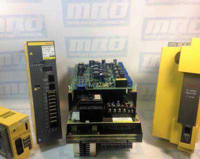
MRO Electric and Supply has new and refurbished FANUC CNC parts available now such as motors, servo amps, spindle ampsdisplays and controls, power supplies, I/O modules,  and PCBs.

We also offer repair pricing. For more information, please call 800-691-8511 or email sales@mroelectric.com.
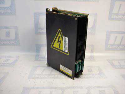
FANUC A16B-1212-0100 Power Supply Unit

MRO Electric and Supply has new and refurbished FANUC A16B-1212-0100 power supply units available now, and also offers repair pricing. For more information, please call 800-691-8511 or email sales@mroelectric.com.
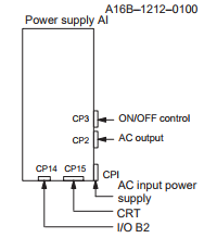
a16b-1212-0100 wiring diagram
A16B-1212-0100 Wiring Diagram

The A16B-1212-0100 is an easy to mount CNC power supply that is designed to connect directly to the System 0 master PCB. All its AC inputs and DC outputs are linked via connectors. Because the power supply unit has a built-in input unit function, it is not necessary to prepare a a separate relay or input unit for switching the AC input on and off. The AC input can be connected directly to the power supply unit. The unit has an AC service outlet, which is switched on and off simultaneously with the power supply unit. This AC service outlet can be used to supply power to a unit such as a fan motor. Sometimes the alternate FANUC part number P007P0355 is used.

FANUC A16B-1212-0100 Input / Output Connectors

Connector NameDescription
CP1200/220/230/240 VAC input
CP2200/220/230/240 VAC output
(switched on and off simultaneously with the power supply unit)
CP3- Power on/off switch contact signal input.
- External alarm signal input.
- Alarm signal input.
CP12- Supply of +5 V, +15 V, –15 V, +24 V, and +24E to the master
printed–circuit board.
- EN signal output.
CP14- +24E supply for the additional I/O B2 printed circuit board
(for Series 0).
- +24E supply for the connection unit (for Series 15)
CP15+24V supply for the 9” monochrome CRT/MDI unit (for Series 0).

* MRO Electric can offer replacement 9" monitors for your unit.

Descriptions of the A16B-1212-0100 I/O Signals and Display LEDs
    1. AC power supply display LED (green) – When an AC power source is connected to the power supply unit, the LED lights regardless of whether the unit is on or off.
    1. Alarm display LED (red) – If the power supply unit is switched off because of an alarm condition due to a failure such as an output error, the alarm display LED lights and remains on until the alarm condition is cleared by pressing the OFF switch or shutting down the AC power supply.
  1. ENABLE signal EN (output) – This TTL level signal indicates that all DC outputs are normal. It becomes low if an output failure is detected in any circuit.
  2. Power supply on/off control signal ON–OFF–COM (input) – If two switches are connected to this circuit as shown below, pressing the ON switch turns on the power supply unit, while pressing the OFF switch turns the unit off. If an alarm occurs in the power supply unit, and the alarm display LED lights in red, however, pressing the ON switch will not turn on the power supply unit. In this case, it is necessary to remove the cause of the alarm and press the OFF switch. Pressing the OFF switch clears the alarm condition. Subsequently pressing the ON switch turns on the power supply
    unit.
  3. External alarm signal AL (input) – When a contact signal from another unit or external power supply becomes ”closed,” the ENABLE signal of this power supply unit becomes low, thus immediately turning off the power supply unit.
  4. Alarm signal FA–FB (output) –  This contact signal indicates the state of all DC outputs. The contact is open when all the DC outputs are normal. It is closed if an output failure is detected in any DC output circuit. If an external alarm signal (item 5) is connected, the FA–FB contact opens, when all DC outputs are normal and the external alarm signal is ”open.” The contact closes when the external alarm signal becomes ”closed.”
Adjustments and Settings

The FANUC A16B-1212-0100 power supply unit requires no adjustment or setting. Do not attempt to adjust the reference voltage (=10.00V) at A10 unless absolutely necessary, because the reference voltage has been adjusted during unit test; merely confirm the voltage across A10 and A0 of check connector CP16. If the reference voltage at A10 falls outside the rated range, set it to 10.00V, using VR11, while measuring the voltage with a digital voltmeter. Rotating VR11 clockwise increases the voltage at A10. After the power supply unit is replaced, always to check the reference voltage at A10.

a16b-1212-0100
A16B-1212-0100
FANUC Controls Alarms

FANUC Troubleshooting Manual – FANUC CNC FAQ

FANUC CNC machine is an extremely useful tool – but like many tools, it’s susceptible to breaking. Read on to learn common FANUC issues and how to best troubleshoot to solve the problem.

What is the proper method to test a motor for a short?
The proper way to troubleshoot a FANUC motor for a short is to first lock out the machine, remove the cable from the drive, and test all three motor phases to ground with a megohmmeter. This will test both the motor and the cable for problems.

Why am I getting errors when I connect to my FANUC drive’s RS-232 port?
There are a number of explanations for these errors. The RS-323 port is a high-fail component on a FANUC drive as it is very susceptible to electrical surges. However, the RS-232 cable is also another high-fail item. Ensure that you are using a cable that is known to be functional when communicating. Otherwise when you attempt to read-in or punch-out a cable, you will get an 086 alarm that is going to indicate that the cable is incorrect, or that the port has failed.

To test whether the cable or the port has failed, take a known good cable and insert it into the RS-232 port. Next, set your machine up to receive a file. The screen should being to flash “READ”. Next, transmit your file into the machine tool. If the machine continues to flash “READ” (or “LSK” on modern controls) but never receives the file, you have a defective communications port on either the memory board or the master board. These boards or your machine will need to be sent in for repair.

What is an Axis Communications Error?
An Axis Communications Error indicates a communications problem between the motor encoder and the CNC control. This can be caused by the motor encoder itself,  the cable going to the encoder, or the axis control card the cable is plugged into.

What is an Excess Error Alarm and why is it caused?
Generally, an Excess Error means that the machine has moved beyond its allowable tolerance. The CNC has told the FANUC servo drive to make a move, the servo drive moves the motor,  which in turn moves the encoder. As the machine moves, there will be some deviation. This deviation is known as the Excess. The parameters set how much deviation/excess should be allowed.

These errors can be caused by a variety of problems. For example, a dull tool can caused the axis to be pushed out of position which results in a deviation error. Debris build up can cause deviations while the machine is stopped. Additionally, a failed servo drive can also cause deviation errors.

What is FANUC 401 Servo Alarm?
Alarm 401 is a very generic FANUC alarm. It simply means that the servo’s did not obey. The CNC, which is in charge of the servos, tells the servo drives to turn on and remain on. If for whatever reason the servo drive turns itself off without the permission from the CNC, the CNC will generate a 401 alarm. This alarm will usually occur with other alarms, such as the 414 Alarm.

What is FANUC Servo Alarm 414?
The FANUC Servo Alarm 414 is an alarm issued by the CNC that says a problem has been found in either the servo drive or the feedback system. The alarm will show which axis is causing the problem. To identify the specifics of this alarm, you must go into the CNC diagnostics page. Diagnostics number 200 on the 16th row will indicate what is causing the problem.

What is the difference between a High-Current Alarm and an Over-Current alarm?
A high current is an abnormal current that can be caused by noise. When the system detects this, it will generally shut the machine down and generate a High-Current Alarm. This FANUC alarm code is usually caused by defective servo drive or cooling contamination inside of the motor windings or cable.

An Over-Current Alarm indicates that too much current has flowed through the DC link. This is usually caused by a short in the system, an unplanned contact, a defective transistor module, or dull tooling attempting to make a cut. 

Why do I get a Soft Overtravel Alarm when I try to reference a newly installed motor?
When the CNC power down, it remembers its last known position. When you restart the machine, an incremental encoder will ask that the machine be re-positioned. When you try to do a re-reference of the machine tool, and it doesn’t agree with where the last known position was, the machine with automatically go into a default that indicates a Soft Overtravel Alarm. These alarms can occur as any point in the travel of the machine. To bypass this alarm, power the machine down and hold down the key with the letter “P” on it as well as the “Cancel” button (at the same time). Then power the machine up while you continue to hold down both of these buttons. If you do this, the machine will ignore all Soft Overtravels until the first zero referenced position has been done on that axis, and will clear the Soft Overtravel Alarms.

I unplugged my AC or DC FANUC motors, and now I am getting a 300APC Alarm. What is that?
A 300APC Alarm indicates that you are using an absolute pulse coder. The difference between an absolute pulse coder and a incremental pulse coder deals in the memory retention of the position. Using a CNC control with an incremental pulse coder, you must reference the machine every time you turn the machine back on.

With an absolute pulse coder, there is a battery backed memory that retains the position of the machine tool when it powers down. When the CNC machine turns back on, it asks the encoder its position, and the encoder then responds back with its current position. If it is within tolerance of where it was when it shut down, the CNC will continue to run the program. However, if you lose the memory retention due to an encoder cable being unplugged, you will end up with the 300 level APC alarms. These FANUC alarms simply signify that the machine must be re-referenced. The re-referencing procedure is determined by the machine tool builder – consult your machine tool builder manual for the proper operation.

If this FANUC troubleshooting manual was not comprehensive enough, MRO Electric stocks new and refurbished FANUC products, and also offers reliable FANUC repairs. Please call 800691-8511 or email sales@mroelectric.com for a quote.

FANUC Servo & Spindle Motor Repair

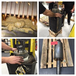
MRO Electric and Supply provides fast and reliable FANUC servo motor repairs on all types of FANUC motors. Our factory-trained repair technicians have years of expertise with FANUC servo systems, and our facility provides them best-in-class testing equipment that will have your FANUC motors repaired, tested, and aligned precisely to the manufacturer’s specifications.

Our large inventory of spare parts and replacement components allow for us to repair your motor quickly to get you back up and running with minimal downtime. MRO Electric is able to recondition and test each of your motor’s components. This includes performing re-windings and replacing bearings, as well as repairing armatures, housings, encoders, resolvers, output shafts, and flanges.

FANUC Servo Motor Repair

As one of the nation’s leading FANUC servo motor repair specialists, MRO Electric places a strong emphasis on reliable customer service, great pricing, fast turnaround, and quality repairs. Each of our FANUC servo repairs come with a minimum 12-month warranty. MRO Electric can repair all FANUC motors and parts, both new and old.

FANUC Motor Repair
FANUC Motor Repair

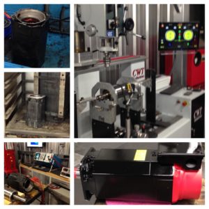
Once your motor is received, it is thoroughly cleaned and reconditioned. Our trained technicians disassemble, inspect, and troubleshoot each individual motor component. After each non-functioning component is replaced or repaired, we test motor function fault, brake, encoder, and thermistors. We then commission the motor using one of our drives, testing it in both forward and reverse for at least an hour.

MRO Electric also stocks both new and refurbished FANUC motors with rush shipping options available. If you require a working motor immediately, you can take advantage of our core exchange policy to return your non-functioning motor in for credit.

We recently rebuilt some Fanuc AC Spindle Motors, including one motor part number A06B-0828-B302. The customer was in a rush and needed this 357 lb motor so that he could get back up and running right away. We didn’t have the motor in stock, but we did have all of the parts in stock to build the motor. Check out all of our Fanuc CNC products on our website.

Within 3 days we were able to rebuild, repaint, and fully test the motor with our FANUC Spindle drives to get it ready to go back out via freight to the customer, so they were back up and running in less than a week.

Our rebuilds for these size motors usually take 2-3 days, so we were right on schedule for this Fanuc motor. We have the full list of motors that we stock and repair here, and you can email sales@mroelectric.com for more info. We also have pictures of the finished product below as an example.

For a free FANUC servo motor repair quote, please email sales@mroelectric.com or call 800-691-8511.  For more information on our FANUC repair capabilities, you can visit our FANUC Repair page.

FANUC Drive Repairs from MRO Electric and Supply

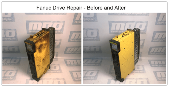
Here at MRO Electric and Supply, our repair shop is designed to provide the highest quality drive repairs on all FANUC spindle and servo amplifiers. With a variety of testing platforms and a large stock of replacement components, we can fully repair and refurbish your FANUC drive to “like new” condition.

Each of our FANUC Drive repairs come with a 12-Month Warranty.

Our Process:

  1. Inspection / Disassembly
    When your non-functioning FANUC drive is first received, our repair technicians go to work inspecting, disassembling, and thoroughly cleaning your unit.  Throughout this process, we will evaluate your drive to determine the primary cause of failure.
  2. Component Replacement
    Our technicians test and replace any non-functioning components on your FANUC Drive. We also replace any worn parts, as well as components that are prone to failure. This includes resistors, diodes, IGBT’s, capacitors, electrolytic caps, relays, and fans. We have one of the largest stocks of FANUC circuit boards on the globe. We continue to troubleshoot and replace components until we are confident that your FANUC drive can move onto the testing phase.
  3. Testing
    With our numerous testing platforms, we perform a variety of dynamic functional tests on your FANUC drive to ensure reliability. After these procedures, your FANUC drive is left to run overnight in our facility to certify its consistency.
  4. Shipping
    Once your FANUC drive has passed our strict testing and quality control procedures, it is carefully packaged and shipped back to you in perfect working condition.
Our repair pricing can save you up to 75% compared to buying new drive. Save time and reduce costs by having your FANUC drive refurbished by the experts here at MRO Electric. 
For more FANUC Drive repair information or to request a free quote, please call 800-691-8511 or email sales@mroelectric.com.
Human Machine Interface (HMI) Retrofitting

At MRO Electric and Supply, we are experts at retrofitting older HMIs with a new interface that is clean, modernized, and still works with your system.

Take this older Fanuc HMI as an example. The old CRT display has begun to fade out, making its use inefficient and none user-friendly. Old CRT screens are also prone to overheating, and they take up a lot of much needed space.

Fanuc HMI
Fanuc HMI Pre-Retrofit

A new LCD retrofitted screen can give you more accessibility, brighter displays, and user-friendly colors. MRO Electric can quickly update your FANUC Displays and HMIs at a fraction of the cost of replacing your whole HMI. You also don’t have to rewrite your programming, or waste time and resources replacing your whole system.

Fanuc HMI next to LCD Retrofit
Fanuc HMI next to its LCD Retrofit

Below is a fully retrofitted Fanuc HMI with an LCD monitor. This lighter, energy-efficient replacement adds years of life and service to existing legacy equipment, and eliminates potential future downtime. In addition, all of our HMI repairs come standard with a 12 month warranty.

Newly Retrofitted Fanuc HMI

Get in touch with us today to learn more about this cost effective solution for your HMIs. You can request a quote by calling 1-800-691-8511 or by emailing sales@mroelectric.com.