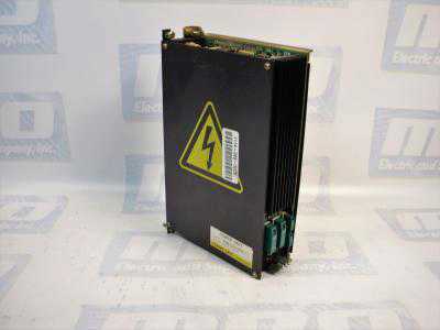
MRO Electric and Supply has new and refurbished FANUC A16B-1212-0100 power supply units available now, and also offers repair pricing. For more information, please call 800-691-8511 or email sales@mroelectric.com.
The A16B-1212-0100 is an easy to mount CNC power supply that is designed to connect directly to the System 0 master PCB. All its AC inputs and DC outputs are linked via connectors. Because the power supply unit has a built-in input unit function, it is not necessary to prepare a a separate relay or input unit for switching the AC input on and off. The AC input can be connected directly to the power supply unit. The unit has an AC service outlet, which is switched on and off simultaneously with the power supply unit. This AC service outlet can be used to supply power to a unit such as a fan motor. Sometimes the alternate FANUC part number P007P0355 is used.
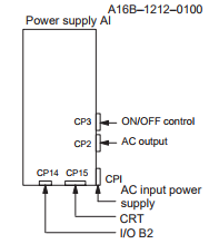
FANUC A16B-1212-0100 Input / Output Connectors
| Connector Name | Description |
|---|---|
| CP1 | 200/220/230/240 VAC input |
| CP2 | 200/220/230/240 VAC output (switched on and off simultaneously with the power supply unit) |
| CP3 | - Power on/off switch contact signal input. - External alarm signal input. - Alarm signal input. |
| CP12 | - Supply of +5 V, +15 V, –15 V, +24 V, and +24E to the master printed–circuit board. - EN signal output. |
| CP14 | - +24E supply for the additional I/O B2 printed circuit board (for Series 0). - +24E supply for the connection unit (for Series 15) |
| CP15 | +24V supply for the 9” monochrome CRT/MDI unit (for Series 0). * MRO Electric can offer replacement 9" monitors for your unit. |
Descriptions of the A16B-1212-0100 I/O Signals and Display LEDs
-
- AC power supply display LED (green) – When an AC power source is connected to the power supply unit, the LED lights regardless of whether the unit is on or off.
-
- Alarm display LED (red) – If the power supply unit is switched off because of an alarm condition due to a failure such as an output error, the alarm display LED lights and remains on until the alarm condition is cleared by pressing the OFF switch or shutting down the AC power supply.
- ENABLE signal EN (output) – This TTL level signal indicates that all DC outputs are normal. It becomes low if an output failure is detected in any circuit.
- Power supply on/off control signal ON–OFF–COM (input) – If two switches are connected to this circuit as shown below, pressing the ON switch turns on the power supply unit, while pressing the OFF switch turns the unit off. If an alarm occurs in the power supply unit, and the alarm display LED lights in red, however, pressing the ON switch will not turn on the power supply unit. In this case, it is necessary to remove the cause of the alarm and press the OFF switch. Pressing the OFF switch clears the alarm condition. Subsequently pressing the ON switch turns on the power supply
unit. - External alarm signal AL (input) – When a contact signal from another unit or external power supply becomes ”closed,” the ENABLE signal of this power supply unit becomes low, thus immediately turning off the power supply unit.
- Alarm signal FA–FB (output) – This contact signal indicates the state of all DC outputs. The contact is open when all the DC outputs are normal. It is closed if an output failure is detected in any DC output circuit. If an external alarm signal (item 5) is connected, the FA–FB contact opens, when all DC outputs are normal and the external alarm signal is ”open.” The contact closes when the external alarm signal becomes ”closed.”
Adjustments and Settings
The FANUC A16B-1212-0100 power supply unit requires no adjustment or setting. Do not attempt to adjust the reference voltage (=10.00V) at A10 unless absolutely necessary, because the reference voltage has been adjusted during unit test; merely confirm the voltage across A10 and A0 of check connector CP16. If the reference voltage at A10 falls outside the rated range, set it to 10.00V, using VR11, while measuring the voltage with a digital voltmeter. Rotating VR11 clockwise increases the voltage at A10. After the power supply unit is replaced, always to check the reference voltage at A10.
Updated on March 5, 2020 by Brian Hughes
Hello, We are looking for a reburbished Fanuc Power Supply A16B.1212-0100-01.
We can take it in Laredo, Texas 78041 vía FEDEX .
Can you quote one piece ?
Tanks so much, Elva de la Fuente.