sinumerik 840d sl

Siemens SINUMERIK 840D SL: Product Spotlight & Alarms

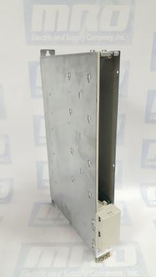
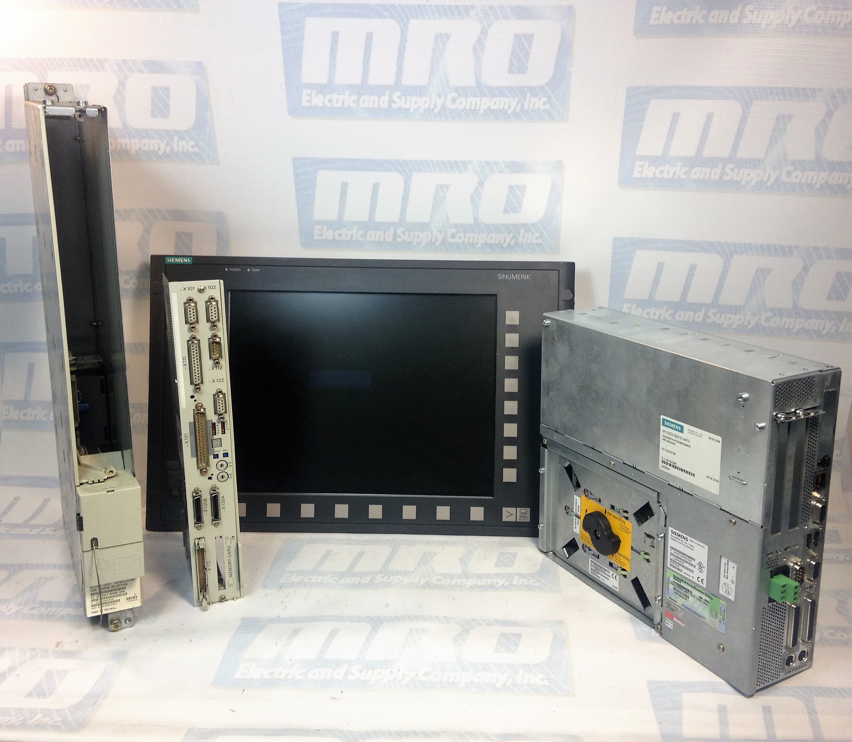
The Siemens SINUMERIK 840D sl is a popular open CNC for modular and premium machining concepts with powerful and dynamic system functions that can be used for a wide range of applications. The CNC system is drive based, and can handle up to 93 axes or spindles and any number of PLC axes. The 840D sl can be used in combination with SINAMICS S120 drives and SIMATIC S7-300 PLCs. The system’s powerful hardware architecture and intelligent control systems ensure machining with the highest level of performance and precision. Additionally, there are a number of solutions that allow for easy IT integration.

The SINUMERIK 840D sl can be used for a wide range of applications including:

  • Turning
  • Milling
  • Gear Machining
  • Grinding
  • Machining Composites
  • Handles and CNC Machining using Robots
  • Nibbling, Waterjet Cutting, Laser Machining, & Plasma Machining
  • Multitasking

The SINUMERIK 840D sl has extremely high precision and performance with accuracy up to 80-bits nano. Its dynamic feed forward control ensures that following error is completely compensated for. With its superb algorithms such as Look Ahead, this system can perform at maximum speed with the same level of performance. The SINUMERIK system also minimizes idle time to keep your production levels at maximum capacity. It can handle kinematic transformations with ease, and sets the standard in energy efficiency. The SINUMERIK 840D sl has a number of integrated safety functions to protect personnel and other machines.

Below is the Siemens SINUMERIK Alarm List:

400000PLC STOP %1 Definitions: PLC not in cyclic mode. Travel with the machine is not possible. %1: 1 Ready(User program has not been started) 2 Break (User program has been interrupted) 3 Error (Other PLC alarm with PLC Stop active) Reaction: Alarm display. Remedy: Rectify other PLC alarm; Switch on menu in PLC stop position or test user program. Program Continuation: Alarm display showing cause of alarm disappears. No further operator action necessary.
400001System error %2 Definitions: %1 :Type number With this alarm, internal alarm states are displayed that, in conjunction with the transferred error number, provide information on the cause and location of the error. Reaction: PLC Stop Remedy: Notify Siemens of this error together with the error message. Program Continuation: Switch control OFF – ON.
400002System error %1 Definitions: %1 :Type number Internal error states are displayed with this alarm. An error number is also specified to provide further details about the cause and location of the error. Reaction: PLC Stop Remedy: Report this error to Siemens along with the type number. Program Continuation: Switch control OFF – ON.
400003Faulty connection to the operator panel Definitions: %1 :Type number This alarm displays that the connection to the machine control panel via the MCPA module has been interrupted. Reaction: Mode group not ready for operation Remedy: Check connection to the MCPA module. Program Continuation: Clear alarm with the Delete key or NC START.
400004Code error: %2 network %1 Definitions: %1 :Network number %2 :Internal error code, module type The user program contains an operation which is not supported by the control. Reaction: PLC Stop Remedy: Modify and reload user program. Program Continuation: Switch control OFF – ON.
400006Loss of remanent PLC data Definitions: The following causes are possible: Control handling (e.g. standard PLC deletion, power up with default values) Control handling of power up with backed up data without backing up data in advance Support time exceeded Reaction: Alarm display. Remedy: Update the data required. Program Continuation: Clear alarm with the Delete key or NC START.
400007Operand error: %2 network %1 Definitions: %1 :Network number %2 :Module type Reaction: PLC Stop Remedy: The variable displayed must be checked in the user program for violation of the address range, impermissible data type and alignment errors. Program Continuation: Switch control OFF – ON.
400008Programming tool – version is not compatible %1 %2 Definitions: %1 :Programming tool version This version is not compatible with the product version of the control system. Reaction: PLC Stop Remedy: Translate the user program using a suitable programming tool version and load in the control. Program Continuation: Switch control OFF – ON.
400009Computing time overrun at PLC level: %2 network %1 Definitions: %1 :Network number %2 :Module type Check user program of the corresponding network displayed. Reaction: PLC Stop Remedy: Change user program Program Continuation: Switch control OFF – ON.
400010Arithmetic error in user program: Type %2 network %1 Definitions: Check user program in the specified network. %1Network number, module ID %2 = 1:Division by zero using fixed-point arithmetic 2:Floating-point arithmetic Reaction: PLC Stop Remedy: Change user program. Program Continuation: Switch control OFF – ON.
400011Maximum number of subroutine levels exceeded: %2 network %1 Definitions: %1Network number %2Module ID Check user program in the specified network. Reaction: PLC Stop Remedy: Change user program. Program Continuation: Switch control OFF – ON.
400013PLC user program is incorrect Definitions: The PLC user program in the control is incorrect or is not available. Reaction: PLC Stop Remedy: Reload PLC user program. Program Continuation: Switch control OFF – ON.
400014PROFIBUS DP: power up interrupted, type: %1 Definitions: %1: 1PROFIBUS DP power up interrupted 2Software versions of NC and PLC do not match 3Number of slots per function exceeded 4PROFIBUS DP server not ready Reaction: PLC Stop Remedy: Types 1 to 3:Report error to Siemens Type 4:802D sl – Check and/or replace PCU hardware and/or check MD 11240 Program Continuation: Switch control OFF – ON.
400015PROFIBUS DP: I/O defect: log adr. %1 bus/station: %2 Definitions: The PLC-AWP is using I/O addresses which are not available. %1Logical I/O address %2Bus number/station number Causes of error: Bus peripheral has no voltage Bus address set incorrectly Bus connection faulty Active MD 11240 (SDB configuration) is set incorrectly Reaction: PLC Stop Remedy: Rectify the error using the error cause Program Continuation: Switch control OFF – ON.

The SINUMERIK 840D sl can be used in many different industries. Its customization solutions allow it to fulfill the requirements of even highly regulated industries. There are even support services and solutions provided for specific niches.
SINUMERIK 840D SL Applicatons

MRO Electric offers a variety of support services for the SINUMERIK 840D sl. These include providing new spares, refurbished components, and repair services. If you are in need of a replacement part or FANUC repairs, please call us at 800-691-8511 or email sales@mroelectric.com.
tsxcusbmbp

Schneider Electric TSXCUSBMBP: Beyond the User Manual

Need a replacement TSXCUSBMBP? Request a Price Quote Now.

The Schneider Electric TSXCUSBMBP is a USB Modbus Plus Communications Adapter. In this guide, we will show you how to install the hardware, configure the driver software, and use the Modbus Plus network diagnostics features of the driver software.

Important: The least versions of the TSXCUSBMBP driver to run on Win Server 2012 R2 are driver versions 8.0 and 8.1.

The TSXCUSBMBP is designed to bridge the gap between a USB connection and the Modbus Plus network. It combines hardware and software together in one simple and single device. The module has its own Modbus Plus node address which can be set through the TSXCUSBMBP driver software. This module allows software applications using the serial Modbus RTU communications to connect on the high-speed Modbus Plus network, as well as provide diagnostic capabilities to the Modbus Plus network.

Most Win32 Applications that support serial Mdubus communications can use a Modicon TSXCUSBMBP to connect on a Modbus Plus network. A VSP (Virtual Serial Port) is what redirects communications from Concept, Unity, ProWorx32 and other programs to the TSXCUSBMBP communications adapter. After the VSP is installed, it will create one serial port with the port reference as defined in the module’s driver software. When configuring the Modbus application software, this port reference is selected as the serial port for the application to use. The routing table is used to associate Modbus Slave IDs with 5-byte Modbus Plus routing paths which allow the application software to communicate with any Modbus Plus device within range on the network.

The TSXCUSBMBP’s hardware consists of a box with a USB cable from one end (which connects to the PC) and a standard Modbus Plus DB9 connector on the other end (for the Modbus Plus network). Local signalling LEDs on the top cover of the device tell you the presence of power from the USB port and the state of the Modbus Plus network – no external power supply is required.

TSXCUSBMBP Installation

To install the TSXCUSBMBP, you will need the following:
– Windows XP Operating System with service pack 2, or Windows 2000 with Service Pack 4 or greater.
– 1 MB of free disk space.
– Minimum of 256 MB of RAM.
– One free USB port or a USB Hub that supports USB 1.1 or greater.

If a previous version of the TSXCUSBMBP was installed, the VSP component of the driver must be manually uninstalled using Device Manager before a new version can be installed. After this, the new driver should be installed before connecting the new TSXCUSBMBP to the PC. After the new driver is installed, connect the TSXCUSBMBP and install using the New Hardware Wizard. After completing the instructions, you should see a message stating “Your new hardware is ready to use.” Restart your computer, and the device should be fully functional. If the driver starts up before the TSXCUSBMBP is connected, then it will be necessary to re-scan for adapters so the driver can detect it.

TSXCUSBMBP Configuration

To configure the module, you will need to do the following:

1. Configure the Modbus Plus Node Address
The communications adapter must be assigned a Modbus Plus node address to communicate on the network. Select “Settings” and then type the address in the appropriate box. When complete, hit “Save”.

2. Configure the Slave Response Timeout
The slave response timeout is used by the module each time it sends a request from an application out on the network to a slave device. Use the manual to determine the appropriate value that should be used with your system. Select “Settings” and then type the value in the appropriate box. When complete, hit “Save”.

3. Configure the Virtual Serial (COM) Port
To do this, select “Virtual Modbus Port.” Select the desired COM port from the list available. When complete, click “Save”.

If you experience any problems while configuring your adapter, please use the table below to determine the appropriate error code given by the LEDs, if applicable. As always, refer to the user manual for more complete information.

TSXCUSBMBP Error Codes
MRO Electric carries both New and Refurbished TSXCUSBMBP Communication Adapters. For more information on this module or to request a price quote, please call 800-691-8511 or email sales@mroelectric.com.
6SN1123-1AA00-0CA2

Siemens 6SN1123-1AA00-0CA2: Beyond the User Manual

The Siemens 6SN1123-1AA00-0CA2 is a Simodrive 611, 1 Axis Power Module. With the control module, the 6SN1123-1AA00-0CA2 forms the drive module for feed or main spindle applications. The module provides power to the control boards as well as the connected motors. It can be used to operate a variety of Siemens and 3rd party motors. This module is graded according to a certain rating and can be supplied with three different cooling techniques. The module is equipped with overload protection. When this is dimensioned properly,  it prevents both the cables and motors from being overloaded. the power module has two operating modes – one for Feed drives and another for Main spindle drives.

The 6SN1123-1AA00-0CA2 can be used for a variety of solutions due to its modular and space saving attributes. The module’s output limits can be modified by the control module in use. The drive modules can be operated from both an unregulated and regulated supply modules belonging to the Simodrive 611 drive system. The power module draws its supply required to control the motors from the DC link.

Then installing a control board into the 6SN1123-1AA00-0CA2, make sure the following is observed:

  1. Ensure that the power module is in a no-voltage condition.
  2. Check that the memory module is inserted and locked into place in the control board.
  3. Insert the control board into the power module.
  4. Tighten the screws retaining the board (2 on front panel).
  5. Connect the front panel of the board corresponding with its applicable connection diagram. The mating connectors must be inserted at the appropriate interface.
MRO Electric stocks both new and refurbished 6SN1123-1AA00-0CA2 Power Modules. For more information or to request a quote, please call 800-691-6511 or email sales@mroelectric.com.

6SN1123-1AA00-0CA2
6SN1123-1AA00-0CA2

Control Techniques Lineup

Benefits of Buying Refurbished Industrial Automation Equipment

At MRO Electric and Supply, we offer a wide range of repaired, refurbished and reconditioned automation products for each of our manufacturer lines. We never supply used, untested, second-hand parts. Each of our refurbished parts is fully cleaned, serviced, functionally tested, and upgraded to optimal working order before being made available for sale. We also place each of our reconditioned products in like-new packaging for easy identification, transportation, and storage.

Benefits of Refurbished Automation Products:

1. Availability
For many obsolete and legacy automation product lines, finding new, unused parts can be a challenging task. Oftentimes, searching for unavailable new parts can cause unreasonably long lead times which increases the risk of downtime. MRO Electric stocks a variety of refurbished products with same-day and next-day shipping options, while keeps the risk of downtime to a minimum.

2. Price
Refurbished products tend to be significantly less expensive than new parts. MRO Electric offers many refurbished items for up to 75% less than their new counterparts. This deep discounting allows our customers to stock up on spares while minimizing their costs.

3. Equivalence
Purchasing an exact replacement prevents compatibility issues versus upgrading to a newer component. For some manufacturers, it is better to stick with tried and true systems than risk purchasing a different part that may not function correctly with their process.

4. Reliability
Just because a part has been refurbished does not mean that it won’t last as long as new. Additionally, many of our refurbished parts have seen little or no use throughout their lifetime. We are extremely confident in the reliability of our refurbishment process, and warranty all of our products for a minimum of 12 months.

                            Our Top Manufacturers
 Siemens     FANUC                              Yaskawa          ABB
Control Techniques
Yaskawa V1000

Yaskawa V1000 – Compact Vector Control Drive

The Yaskawa V1000 is a compact current vector drive with dual microprocessor logic. There are 3 primary models: 200V 3-Phase Input, 200V Single-Phase Input, and 400V 3-Phase Input.  It is possible to run the drive without connecting the digital I/O wiring.

It is important when installing Yaskawa V1000 drives that proper electrostatic discharge (ESD) procedures are taken. Failure to comply could result in an ESD discharge that could damage the drive circuitry. If the drive is being operated at low speeds, the cooling effects are diminished and motor temperatures can increase which can lead to overheating. Continuously operating an oil-lubricated motor in the low speed range may result in burning.

A dynamic braking resistor can be used with the V1000 series. Dynamic braking helps bring the motor to a smooth and rapid stop when it is working with loads of high inertia. As the drive lowers the frequency of a motor with high inertia connected, regeneration occurs. This can cause over-voltage when the regenerative energy flows back into the DC bus capacitors. A braking resistor can help prevent these overload errors from occurring.

The drive functions are devided into 2 primary groups that are accessible through the Yaskawa V1000’s digital LED operator. Drive mode allows for motor operation and parameter monitoring. Parameter settings cannot be changed when functions are accessed in drive mode. However, alarm information and history can be accessed in drive mode. Programming mode allows access to the setup. There you can adjust and verify drive parameters as well as Auto-Tuning. The drive will not allow motor operation changes such as start and stop when the LED is accessing a function Programming mode. The V1000 is set to Drive mode when it is first powered up. The Up and Down arrow keys can be used to switch displays.

MRO Electric and Supply carried new and refurbished Yaskawa V1000 Drives. For more information or to request a quote, call 800-691-8511 or email sales@mroelectric.com.

Yaskawa V1000
Yaskawa V1000

Yaskawa CIMR-AU4A0038FAA A1000 Drive – Product Spotlight

The CIMR-AU4A0038FAA is a three-phase 400 Volt AC Drive. There are two modes on this AC drive – Programming Mode and Drive Mode. In Drive Mode, the user can operate the motor and observe U monitor parameters. Parameter settings cannot be changed or edited while in Drive Mode. In Programming Mode, the user can edit and verify parameter settings and perform Auto-Tuning. When the drive is in Programming Mode, it will not accept a Run command unless b1-08 is set to 1. If b1-08 is set to 0, the drive will only accept a Run command in Drive Mode. After editing the parameters, the user must exit the Programming Mode and enter Drive Mode before operating the motor.

Check out our website for all of our Yaskawa products!

Local mode is when the drive is set to accept the Run command from the digital operator RUN key. Remote mode is when the drive can be set to accept the Run command from an external device, such as input terminals or serial communications. Switch the operation between Local and Remote using the LO/RE key on the digital operator or via a digital input. After selecting local, the LO/RE light will remain lit. The CIMR-AU4A0038FAA will not allow the user to switch between Local and Remote during run.

Several Application Presets are available to facilitate setting up the drive for commonly used applications. Selecting one of these presets automatically assigns functions to the input and output terminals and sets a predefined number of parameters to values appropriate for the selected application. An Application Preset can either be selected from the Application Selection menu in the Setup Group or in parameter A1-06. The default parameter setting is 0, which disables the presets. The following setting ranges are listed below:
– 0: Disabled
– 1: Water supply pump
– 2: Conveyor
– 3: Exhaust fan
– 4: HVAC
– 5: Compressor

MRO Electric and Supply stocks a variety of A1000 Drives including the CIMR-AU4A0038FAA. For more information or to request a quote, please email sales@mroelectric.com or call 800-691-8511.

CIMR-AU4A0038FAA
CIMR-AU4A0038FAA

HMIGTO5310

Magelis HMIGTO5310 Touch Panel – Product Spotlight

The HMIGTO5310 (HMI-GTO-5310) is a Modicon Magelis GTO advanced touchscreen panel. It features a 10.4 inch display with a 96 MB flash memory. The panel uses an external power supply of 24 Volts DC, and has a lithium battery for internal RAM. It’s back light lifespan is 50,000 hours at 25 °C. Using an SDHC or SD card, one can add up to 32 GB of data storage to the HMIGTO5310. It also has an internal RAM of 512 kB used to back up data. Using either the panel’s software or its touch panels, a user can control 16 different levels of screen brightness.

The HMIGTO5310 weights precisely 2 kg. It measures 272.5 x 214.5 x 57 mm (W x H x D).  The HMIGTO5310 can be mounted by using 4 screw clamps with flush mounting.

The HMIGTO5310 supports a large number of downloadable protocols, including the Modbus TCP, Siemens Simatic, Rockwell Automation / Allen Bradley, Omron Sysmac, Mitsubish Melsec, FIPWAY, Modbus Plus, Uni-TE, and Modbus. The panel supports a number of integrated connection types, some of which include the Ethernet RJ45, the USB 2.0 ports, COM2 serial links, and a COM1 serial link.  When using the COM2 serial interface, be aware that the serial port is not isolated. The signal ground and frame ground terminals are connected inside the panel. There is risk of electric shock if precautions are not taken. When using the signal ground terminal to connect an external device to the panel, verify that a short circuit loop was not created when you set up the system. Connect the #8 signal ground terminal to remote equipment when the host PLC unit is not isolated. Connect the #8 signal ground terminal to a known reliable ground connection to reduce the risk of damaging the circuit.

When setting up RS-485 communication, the cable diagram for some equipment may require polarization on the terminal side. This terminal does not require any special setting as it handles polarization automatically.

MRO Electric and Supply stocks HMIGTO5310 panels. For more information or to request a quote, please contact us at 800-691-8511 or at sales@mroelectric.com.