Siemens Sinamics AOP30 Operator Panel: Beyond the User Manual

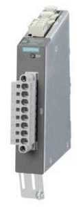
The AOP30 is an operator panel with graphical display/membrane keyboard and has a part number of 6SL3055-0AA00-4CA5. The device can be installed in a cabinet door which is between 2 mm and 4 mm thick. It is an input/output device for converters of the SINAMICS series, preferably for cabinet installation. The AOP30 includes the following features:

  • Graphical backlit LCD display for plain text display and a bar display of process variables
  • LEDs for display of the operating states
  • Help function describing causes of and remedies for faults and alarms
  • Keypad for operational control of a drive
  • Local/remote switchover for selecting the operating location
  • Numeric keypad for input of setpoint or parameter values
  • Function keys for guided navigation in the menu
  • Two-stage safety concept to protect against accidental or unauthorized changes to settings
  • Front panel with degree of protection IP55

aop30

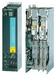
The current operating states, setpoints and actual values, parameters, indices, faults and alarms are displayed on the display panel. Desired language must be downloaded to the AOP30 prior to commissioning. If just one CU320‑2 Control Unit controls several power units (multi-motor drives) in the SINAMICS S120 drive system, the parameters, alarms and faults of all the connected devices can be simultaneously displayed and processed on the AOP30 Advanced Operator Panel.

The AOP30 Operator Panel can be used for the following activities:

    • Parameterization
    • Monitoring status variables
    • Controlling the drive
  • Diagnosing faults and alarms

Has your AOP30 module failed? As with all of our services, our repairs come with a 12 month guarantee. Our repair service is based on doing the right job, and getting your part back to you as soon as possible. Every part we refurbish is tested to make sure they work the way they are supposed to. Our factory-trained technicians have many years working with Siemens products.

For a free AOP30 repair quote, please email sales@mroelectric.com or call 800-691-8511.  For more information on our Siemens repair capabilities, you can visit our Siemens Repair page.

Siemens Sinamics TM120 Terminal Module: Beyond the User Manual

Terminal Modules are used to add further input and output interfaces to the S120 drive system. Terminal Modules are connected to the Control Unit using DRIVE-CLiQ.  DRIVE-CLiQ is a proprietary networking system by Siemens that aims to prevent packet loss and removes some of the collision handling capability. This allows for a high speed deterministic system, but also means that the protocol is not suitable for wireless or slip-ring communication. The TM120 module is used in evaluating temperatures. The temperature is monitored for the following sensors:

  • PT100
  • PT1000
  • KTY84
  • Bimetallic NC contact

The TM150 features 2 DRIVE-CLiQ interfaces, 4 temperature sensor inputs, and one power supply.

tm120

The part number for the Siemens SINAMICS TM120 terminal module is 6SL3055-0AA00-3KA0.

The SINAMICS TM120 is just one of many additional components that are available for S120 systems. These control units significantly reduce system costs, as they increase functionality for positioning, safety integration, and drive control allowing all these functions to be controlled by one unit versus several. There is also additional flexibility with a high number of programming options and digital inputs. With up to 12 binary inputs, the modules’ high I/O count add ease of use. The additional Ethernet port expands programming options as well.

Does your Siemens SINAMICS TM120 module need to be serviced? As with all of our services, our repairs come with a 12 month guarantee. Our repair service is based on doing the right job, and getting your part back to you as soon as possible. Every part we refurbish is tested to make sure they work the way they are supposed to. Our factory-trained technicians have many years working with Siemens products. Minimize your future downtime today by contacting MRO Electric and Supply right now.

MRO Electric stocks new and refurbished TM120 modules. If you would like a replacement module, please call 800-691-8511 or email sales@mroelectric.com.

Siemens Sinamics CU130 Modules: Beyond the User Manual

The CU130 is an S120 single axis control unit capable of controlling PM340 Power Modules. It clips onto the front of the power module and must be used in conjunction with this. The two versions of the CU130 that were released included the CU130 DP PROFIBUS interface and the CU130 PN PROFINET interface. The respective part numbers include:

All SINAMICS versions are based on a platform concept. Joint hardware and software
components, as well as standardized tools for design, configuration, and commissioning
tasks ensure high-level integration across all components. SINAMICS handles a wide variety of drive tasks with no system gaps. Different SINAMICS versions can be easily
combined with each other.

The following system components are available:

  • Line-side power components, such as fuses, contactors, reactors, and filters
  • Line Modules, which supply power centrally to the DC link
  • DC-link components (optional), which stabilize the DC-link voltage
  • Motor Modules, which act as inverters, receive power from the DC link, and supply the connected motors

SINAMICS is a new series of drives from Siemens designated for the following mechanical and plant engineering applications:

  • Simple pump and fan applications
  • Complex individual drives in centrifuges, presses, extruders, elevators, as well as
    conveyor and transport systems
  • Drive line-ups in textile, plastic film, and paper machines
  • Highly dynamic servo drives for machine tools

Depending on the application, the SINAMICS range offers the ideal version for any drive
task.  Users can choose from many different harmonized components and functions to create a solution that best meets their requirements. MRO Electric and Supply has all of your Siemens needs including SINAMICS, SIMODRIVE, and SINUMERIK modules.

MRO Electric stocks both new and refurbished CU130 Control Units, which is part number 6SL3310-1GE36-1AA3. If you would like to purchase a replacement module, please call 800-691-8511 or email sales@mroelectric.com.

Instructions for Installing a 6055 Spindle Drive to A20B-1001-0120

The following is a list of instructions for installing a 6055 Spindle Drive with the A20B-1001-0120 Spindle Drive PCB:

A20B-1001-0120

Instructions:

  1. Make sure the jumpers on the new spindle PCB match the jumpers on your old spindle PCB.
  2. Remove the software chips from the old spindle PCB and install them onto the new spindle PCB.
  3. If possible, remove the NVRAM chip from the old spindle PCB and install it onto the new spindle PCB. This way you will not have to reprogram the chip as the new spindle will have the same instructions as the previous one.
  4. If possible, remove the DAC chip from the old spindle PCB and install is onto the new PCB. There may not be a DAC chip on your previous board and if that is the case do not worry about it. However if the old board does have the chip, failure to install it correctly into the new board will cause issues.
  5. Make sure to set the 200/230 voltage switch to the same setting it is on the old board. This switch also may not be on all drives.

It is very important to follow the manual and make sure that the chips and cards you are moving around are installed correctly. For instance, if you were to incorrectly install the software chips, not only would the display not show anything, you are leaving open the possibilities for a short and causing yourself even more trouble.

Sometimes you may not have the necessary equipment to make a diagnosis on your motor, but we do. MRO Electric and Supply offers high quality repair services on all motors and spindle drives so you don’t have to worry about it. Please take a look at our website to see all available brands and parts we can service for you. Our rebuilds for these size drives usually only take 2-3 days, which includes rebuilding the part, painting the part, and fully testing the part to ensure top quality. By getting your part back to you as soon as possible, you are able to minimize downtime, and by doing the job right you can have peace of mind knowing that your FANUC drive will now work properly and not be the reason for downtime in the future.

MRO Electric and Supply has new and refurbished FANUC CNC parts available. For more information, please call 800-691-8511 or email sales@mroelectric.com.

Instructions for Installing PCB to A06B-6052-H001/4 and more

The following is a list of instructions for installing the these Spindle Drives:

With the A16B-1100-0080 Spindle Drive PCB.

This guide covers the same installation procedure for the following parts:

spindle drive pcb

Instructions:

  1. Make sure the jumpers on the new spindle PCB match the jumpers on your old spindle PCB.
  2. Check to see the status of the 200/230 voltage switch on the old spindle PCB and set it to the same setting on the new spindle drive. You can locate the switch underneath the lid on smaller drives.
  3. Remove the software chip on the old spindle drive and install it into the new one.
  4. If you used a DAC chip in your old spindle, you can can remove it from your old spindle PCB and install it into your new one.

It is very important to follow the manual and make sure that the chips and cards you are moving around are installed correctly. For instance, if you were to incorrectly install the software chips, not only would the display not show anything, you are leaving open the possibilities for a short and causing yourself even more trouble.

Sometimes you may not have the necessary equipment to make a diagnosis on your motor, but we do. MRO Electric and Supply offers high quality repair services on all motors and spindle drives so you don’t have to worry about it. Please take a look at our website to see all available brands and parts we can service for you. Our rebuilds for these size drives usually only take 2-3 days, which includes rebuilding the part, painting the part, and fully testing the part to ensure top quality. By getting your part back to you as soon as possible, you are able to minimize downtime, and by doing the job right you can have peace of mind knowing that your FANUC drive will now work properly and not be the reason for downtime in the future.

MRO Electric and Supply has new and refurbished FANUC CNC parts available. For more information, please call 800-691-8511 or email sales@mroelectric.com.

FANUC A16B-1212-0100 Power Supply Unit

MRO Electric and Supply has new and refurbished FANUC A16B-1212-0100 power supply units available now, and also offers repair pricing. For more information, please call 800-691-8511 or email sales@mroelectric.com.
a16b-1212-0100 wiring diagram
A16B-1212-0100 Wiring Diagram

The A16B-1212-0100 is an easy to mount CNC power supply that is designed to connect directly to the System 0 master PCB. All its AC inputs and DC outputs are linked via connectors. Because the power supply unit has a built-in input unit function, it is not necessary to prepare a a separate relay or input unit for switching the AC input on and off. The AC input can be connected directly to the power supply unit. The unit has an AC service outlet, which is switched on and off simultaneously with the power supply unit. This AC service outlet can be used to supply power to a unit such as a fan motor. Sometimes the alternate FANUC part number P007P0355 is used.

FANUC A16B-1212-0100 Input / Output Connectors

Connector NameDescription
CP1200/220/230/240 VAC input
CP2200/220/230/240 VAC output
(switched on and off simultaneously with the power supply unit)
CP3- Power on/off switch contact signal input.
- External alarm signal input.
- Alarm signal input.
CP12- Supply of +5 V, +15 V, –15 V, +24 V, and +24E to the master
printed–circuit board.
- EN signal output.
CP14- +24E supply for the additional I/O B2 printed circuit board
(for Series 0).
- +24E supply for the connection unit (for Series 15)
CP15+24V supply for the 9” monochrome CRT/MDI unit (for Series 0).

* MRO Electric can offer replacement 9" monitors for your unit.

Descriptions of the A16B-1212-0100 I/O Signals and Display LEDs
    1. AC power supply display LED (green) – When an AC power source is connected to the power supply unit, the LED lights regardless of whether the unit is on or off.
    1. Alarm display LED (red) – If the power supply unit is switched off because of an alarm condition due to a failure such as an output error, the alarm display LED lights and remains on until the alarm condition is cleared by pressing the OFF switch or shutting down the AC power supply.
  1. ENABLE signal EN (output) – This TTL level signal indicates that all DC outputs are normal. It becomes low if an output failure is detected in any circuit.
  2. Power supply on/off control signal ON–OFF–COM (input) – If two switches are connected to this circuit as shown below, pressing the ON switch turns on the power supply unit, while pressing the OFF switch turns the unit off. If an alarm occurs in the power supply unit, and the alarm display LED lights in red, however, pressing the ON switch will not turn on the power supply unit. In this case, it is necessary to remove the cause of the alarm and press the OFF switch. Pressing the OFF switch clears the alarm condition. Subsequently pressing the ON switch turns on the power supply
    unit.
  3. External alarm signal AL (input) – When a contact signal from another unit or external power supply becomes ”closed,” the ENABLE signal of this power supply unit becomes low, thus immediately turning off the power supply unit.
  4. Alarm signal FA–FB (output) –  This contact signal indicates the state of all DC outputs. The contact is open when all the DC outputs are normal. It is closed if an output failure is detected in any DC output circuit. If an external alarm signal (item 5) is connected, the FA–FB contact opens, when all DC outputs are normal and the external alarm signal is ”open.” The contact closes when the external alarm signal becomes ”closed.”
Adjustments and Settings

The FANUC A16B-1212-0100 power supply unit requires no adjustment or setting. Do not attempt to adjust the reference voltage (=10.00V) at A10 unless absolutely necessary, because the reference voltage has been adjusted during unit test; merely confirm the voltage across A10 and A0 of check connector CP16. If the reference voltage at A10 falls outside the rated range, set it to 10.00V, using VR11, while measuring the voltage with a digital voltmeter. Rotating VR11 clockwise increases the voltage at A10. After the power supply unit is replaced, always to check the reference voltage at A10.

a16b-1212-0100
A16B-1212-0100
6sn1123-1ab00-0ca1

Siemens Simodrive 6SN1123-1AB00-0CA1 Power Supply Module

The Siemens Simodrive 6SN1123-1AB00-0CA1 is a 2 Axes, 50 Amp Power Module with internal cooling. The module’s motor rated current for the 1FT5 series is 25 A, and 18 A for the 1FT6 series. However, the power module can be used with a variety of Siemens and third-party motors. The 6SN1123-1AB00-0CA1 is also equipped with overload protection , which prevents motors and cables from being overloaded.

The 6SN1123-1AB00-0CA1 is part of the Simodrive 611 Converter System that can be used for a variety of purposes, including machine tools, robots and manipulators, mass production, form and tool construction, presses and packing machines, and production machines for glass, wood, stone, and textile. The Simodrive’s compact and modular nature allow it to be used for a variety of manufacturing solutions, and can be easily expanded whenever necessary.

Here are the overall specs for the 6SN1123-1AB00-0CA1:

For Operation of Induction Motors
Nominal Current (A eff): 24
Current for S6-40% (A eff): 32
Peak Current (A eff): 32
Inverter Pulse Frequency (kHz): 3.2
Derating Factor XL (%): 55
Power Loss Total (W): 538
Power Loss Internal (W):184
Power Loss External (W): 250
For Operation of Synchronous Motors
Nominal Current (A eff): 18
Peak Current (A eff): 36
Inverter Pulse Frequency (kHz): 4
Derating Factor XL (%): 55
Power Loss Total (W): 380
Power Loss Internal (W):130
Power Loss External (W): 250
General Technical Data for the Regulated Infeed:
Input Voltage (V DC): Regulated – 600V or 625V  DC; Unregulated- U DC Link=U Supply*1.35.
Maximum Output Voltage (V eff): U a_max = (U DC Link / 1.4)
Minimum Motor Current (A): 3.6
Transistor Limit Current (A): 50
Efficiency: 0.98
Module Width (mm): 100
Weight approx. (kg): 13.5
Maximum Air Flow of Fan (Volumetric Flow m3/hr): 56
Motor Connection: Connectors

The 6SN1123-1AB00-0CA1 can be operated as both a regulated and unregulated power supply for the drives.

MRO Electric has new and refurbished 6SN1123-1AB00-0CA1 Power Modules available. For more information or to request a quote, please call 800-691-8511 or email sales@mroelectric.com.