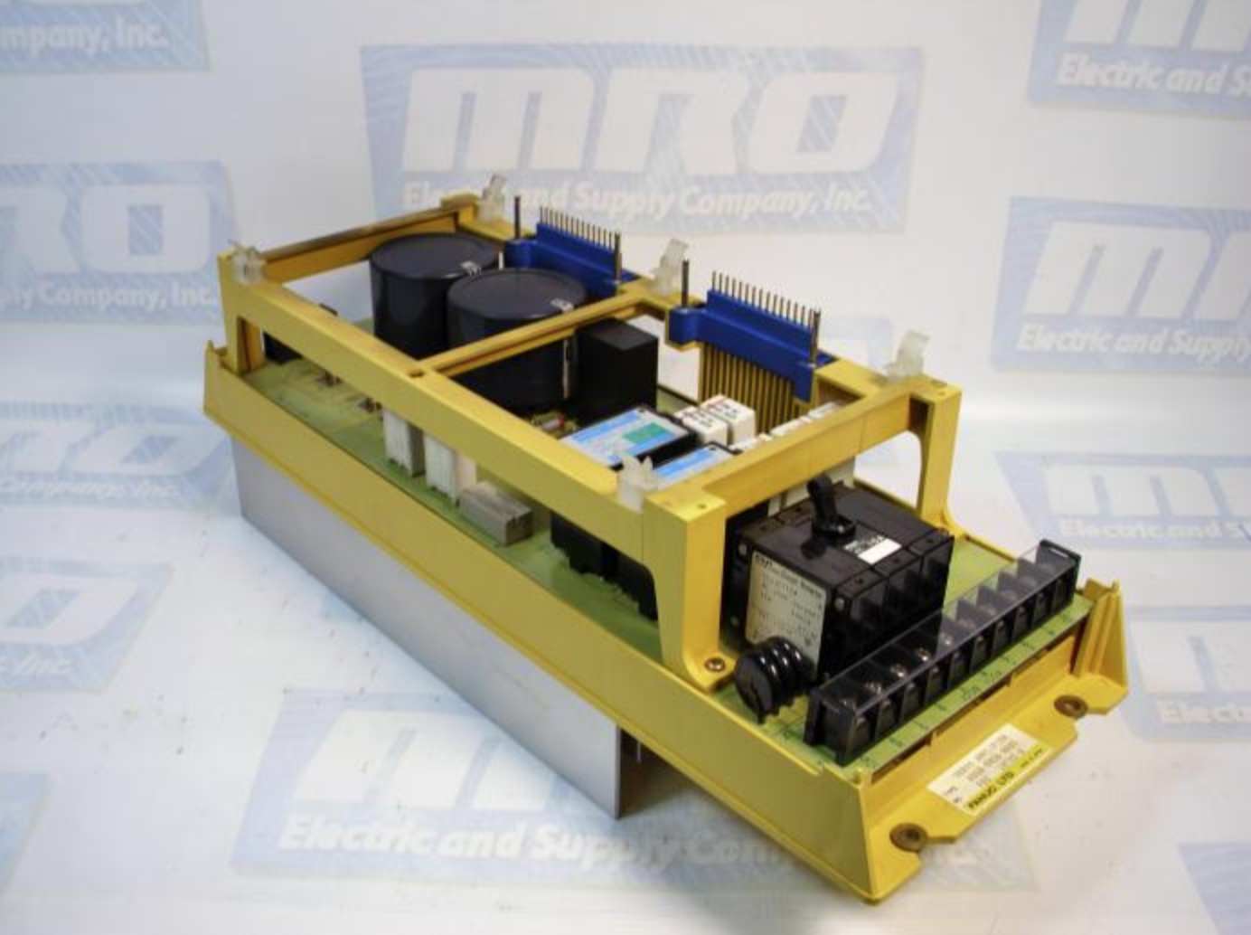
Troubleshooting Fanuc Servo Devices
Recently we had a customer that we helped with troubleshooting a FANUC servo A20B-1003-0090 board that he was installing into an A06B-6058-H005 drive. A handful FANUC troubleshooting options are listed below.
Troubleshooting for the DCAI alarm:
[check items]
- Setting S2 for the S series
- Machine load
- Check connection of separate discharge unit
[Adjustment procedure]
A. Check amplifier setting S2. If the setting is incorrect, go to Cause 1. If the setting is correct, go to A-0.
A-0: Check whether a separate discharge unit is being used. If it is being used, go to A-1. If not being used, go to A-2.
A-1: Check the connection of the separate discharge unit. If the connection is incorrect, go to Cause 2. If connection is correct, go to A-2.
A-2: Check the acceleration/deceleration frequency. If the frequency is too high, go to Cause 3. If the frequency is low enough, go to A-3.
A-3: Replace the servo amplifier. If a DCAL alarm no longer occurs, go to Cause 4. If a DCAL alarm still occurs, go to Cause 3.
[Causes]
1). If the setting S2 of the S series servo amplifier is incorrect, a DC alarm is caused.
2). If the separate discharge unit is connected incorrectly, a DC alarm occurs.
3). Compared to the regenerative power of the amplifier, the regenerative energy of the motor is too large. (The inertia is too large or the acceleration/deceleration frequency is too high.) In this case, try to decrease the acceleration/deceleration frequency or install a separate discharge unit.
4). The discharge transistor (Q1) in the servo amplifier is defective.
MRO Electric and Supply has new and refurbished FANUC CNC products available, including FANUC Servo parts. We also offer repair pricing. For more information, please call 800-691-8511 or email sales@mroelectric.com.
Updated on March 5, 2020 by Brian Hughes