FANUC Controls Alarms

Fanuc Power Supply Alarm Codes – Alpha Series

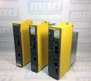
Recently we had a customer who was working on troubleshooting a FANUC CNC Power Supply alarm that he had on a machine. He was wondering what the different codes stood for, so we wanted to go ahead and list the different alarm codes for this series. These codes apply to power supplies that start with the following prefixes. The “X”s after the H will be numbered, so an example part number is A06B-6087-H130.

A06B-6081-HXXX
A06B-6083-HXXX
A06B-6077-HXXX
A06B-6091-HXXX
A06B-6120-HXXX
A06B-6140-HXXX
A06B-6110-HXXX

Here is a list of the alarm codes for these series of Power Supply Modules.

AL01: The main circuit power module (IPM) has detected am Error (PSM-5.5,-11)
Overcurrent flows into the input of the main circuit (PSM-15 to –30).

AL02: A cooling fan for the control circuit has stopped.

AL03: The Temperature of the main circuit heat sink has risen abnormally.

AL04: In the main circuit the DC voltage (DC Link) has dropped.

AL05: The main circuit capacitor was not recharged within the specified time.

AL06: The Input Power Supply is abnormal (open phase).

AL07: In the main circuit the DC Voltage at the DC link is abnormally high.

Be sure to check out our article covering FANUC CNC Troubleshooting Frequently Asked Questions here.

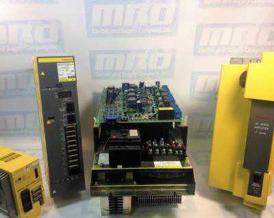
A06B-6087-H130 alarm codes

For more information or to get a quote on a FANUC power supply, please call 800-691-8511 or email sales@mroelectric.com.

We also provide repair services for FANUC Power Supplies.

Testing your Alpha Power Supply Module

The following is a set of instructions to help you get your Alpha Power Supply Module to read “- -” on the display and have a consistent 300 volt DC output:

  1. Turn off the power. Make sure the charge light is off before doing anything. Check for a short between the bottom and top buss bars. If there is a short, disconnect all modules until the short disappears. Once there is no short, continue.
  2. Feed a 3 phase input into L1, L2, and L3 of the the power supply. Between 200V and 220V AC for leg to leg connections and between 100V and 110V AC for let to ground connections.
  3. Feed 200V into the CX1A connector.
  4. Install a jumper onto the top/bottom pins of the grouping of 3 pins on the CX3/MCC cable coming into the power supply.
  5. Install a jumper onto the top two pins of the grouping of 3 pins on the CX4 cable on the power supply.
  6. Make sure that all screws on the PCB are tightly screwed in.

alpha-power-supply

After following this process, your power supply module should now read “- -” and have baseline voltage output. Sometimes you may not have the necessary equipment to make a diagnosis on your motor, but we do. MRO Electric and Supply offers high quality repair services on all motors and spindle drives so you don’t have to worry about it. Please take a look at our website to see all available brands and parts we can service for you. Our rebuilds for these size drives usually only take 2-3 days, which includes rebuilding the part, painting the part, and fully testing the part to ensure top quality. By getting your part back to you as soon as possible, you are able to minimize downtime, and by doing the job right you can have peace of mind knowing that your FANUC drive will now work properly and not be the reason for downtime in the future.

MRO Electric and Supply has new and refurbished FANUC CNC parts available. For more information, please call 800-691-8511 or email sales@mroelectric.com.

FANUC A16B-1212-0100 Power Supply Unit

MRO Electric and Supply has new and refurbished FANUC A16B-1212-0100 power supply units available now, and also offers repair pricing. For more information, please call 800-691-8511 or email sales@mroelectric.com.
a16b-1212-0100 wiring diagram
A16B-1212-0100 Wiring Diagram

The A16B-1212-0100 is an easy to mount CNC power supply that is designed to connect directly to the System 0 master PCB. All its AC inputs and DC outputs are linked via connectors. Because the power supply unit has a built-in input unit function, it is not necessary to prepare a a separate relay or input unit for switching the AC input on and off. The AC input can be connected directly to the power supply unit. The unit has an AC service outlet, which is switched on and off simultaneously with the power supply unit. This AC service outlet can be used to supply power to a unit such as a fan motor. Sometimes the alternate FANUC part number P007P0355 is used.

FANUC A16B-1212-0100 Input / Output Connectors

Connector NameDescription
CP1200/220/230/240 VAC input
CP2200/220/230/240 VAC output
(switched on and off simultaneously with the power supply unit)
CP3- Power on/off switch contact signal input.
- External alarm signal input.
- Alarm signal input.
CP12- Supply of +5 V, +15 V, –15 V, +24 V, and +24E to the master
printed–circuit board.
- EN signal output.
CP14- +24E supply for the additional I/O B2 printed circuit board
(for Series 0).
- +24E supply for the connection unit (for Series 15)
CP15+24V supply for the 9” monochrome CRT/MDI unit (for Series 0).

* MRO Electric can offer replacement 9" monitors for your unit.

Descriptions of the A16B-1212-0100 I/O Signals and Display LEDs
    1. AC power supply display LED (green) – When an AC power source is connected to the power supply unit, the LED lights regardless of whether the unit is on or off.
    1. Alarm display LED (red) – If the power supply unit is switched off because of an alarm condition due to a failure such as an output error, the alarm display LED lights and remains on until the alarm condition is cleared by pressing the OFF switch or shutting down the AC power supply.
  1. ENABLE signal EN (output) – This TTL level signal indicates that all DC outputs are normal. It becomes low if an output failure is detected in any circuit.
  2. Power supply on/off control signal ON–OFF–COM (input) – If two switches are connected to this circuit as shown below, pressing the ON switch turns on the power supply unit, while pressing the OFF switch turns the unit off. If an alarm occurs in the power supply unit, and the alarm display LED lights in red, however, pressing the ON switch will not turn on the power supply unit. In this case, it is necessary to remove the cause of the alarm and press the OFF switch. Pressing the OFF switch clears the alarm condition. Subsequently pressing the ON switch turns on the power supply
    unit.
  3. External alarm signal AL (input) – When a contact signal from another unit or external power supply becomes ”closed,” the ENABLE signal of this power supply unit becomes low, thus immediately turning off the power supply unit.
  4. Alarm signal FA–FB (output) –  This contact signal indicates the state of all DC outputs. The contact is open when all the DC outputs are normal. It is closed if an output failure is detected in any DC output circuit. If an external alarm signal (item 5) is connected, the FA–FB contact opens, when all DC outputs are normal and the external alarm signal is ”open.” The contact closes when the external alarm signal becomes ”closed.”
Adjustments and Settings

The FANUC A16B-1212-0100 power supply unit requires no adjustment or setting. Do not attempt to adjust the reference voltage (=10.00V) at A10 unless absolutely necessary, because the reference voltage has been adjusted during unit test; merely confirm the voltage across A10 and A0 of check connector CP16. If the reference voltage at A10 falls outside the rated range, set it to 10.00V, using VR11, while measuring the voltage with a digital voltmeter. Rotating VR11 clockwise increases the voltage at A10. After the power supply unit is replaced, always to check the reference voltage at A10.

a16b-1212-0100
A16B-1212-0100
6sn1123-1ab00-0ca1

Siemens Simodrive 6SN1123-1AB00-0CA1 Power Supply Module

The Siemens Simodrive 6SN1123-1AB00-0CA1 is a 2 Axes, 50 Amp Power Module with internal cooling. The module’s motor rated current for the 1FT5 series is 25 A, and 18 A for the 1FT6 series. However, the power module can be used with a variety of Siemens and third-party motors. The 6SN1123-1AB00-0CA1 is also equipped with overload protection , which prevents motors and cables from being overloaded.

The 6SN1123-1AB00-0CA1 is part of the Simodrive 611 Converter System that can be used for a variety of purposes, including machine tools, robots and manipulators, mass production, form and tool construction, presses and packing machines, and production machines for glass, wood, stone, and textile. The Simodrive’s compact and modular nature allow it to be used for a variety of manufacturing solutions, and can be easily expanded whenever necessary.

Here are the overall specs for the 6SN1123-1AB00-0CA1:

For Operation of Induction Motors
Nominal Current (A eff): 24
Current for S6-40% (A eff): 32
Peak Current (A eff): 32
Inverter Pulse Frequency (kHz): 3.2
Derating Factor XL (%): 55
Power Loss Total (W): 538
Power Loss Internal (W):184
Power Loss External (W): 250
For Operation of Synchronous Motors
Nominal Current (A eff): 18
Peak Current (A eff): 36
Inverter Pulse Frequency (kHz): 4
Derating Factor XL (%): 55
Power Loss Total (W): 380
Power Loss Internal (W):130
Power Loss External (W): 250
General Technical Data for the Regulated Infeed:
Input Voltage (V DC): Regulated – 600V or 625V  DC; Unregulated- U DC Link=U Supply*1.35.
Maximum Output Voltage (V eff): U a_max = (U DC Link / 1.4)
Minimum Motor Current (A): 3.6
Transistor Limit Current (A): 50
Efficiency: 0.98
Module Width (mm): 100
Weight approx. (kg): 13.5
Maximum Air Flow of Fan (Volumetric Flow m3/hr): 56
Motor Connection: Connectors

The 6SN1123-1AB00-0CA1 can be operated as both a regulated and unregulated power supply for the drives.

MRO Electric has new and refurbished 6SN1123-1AB00-0CA1 Power Modules available. For more information or to request a quote, please call 800-691-8511 or email sales@mroelectric.com.

Fanuc Alpha Power Supply Fault Codes

fanuc cnc

Fanuc Alpha Power Supply Fault Codes

These codes and troubleshooting apply to DC and AC Fanuc power supplies that begin with part number A06B-6077, A06B-6081, and A06B-6087. On the LED display for these units, a “-” will mean that the power supply is not ready while a “0” means that the power supply is powered up correctly. If it reads something other than these two then the power supply has an alarm that needs to be corrected. Below is the list of Fanuc Alpha Power Supply fault codes.

MRO Electric and Supply maintains a comprehensive stock of new and used FANUC Spindle Amps. If you need a replacement part, please call 800-691-8511 or email sales@mroelectric.com.

Alarms
AL-01: Overcurrent in the Main Power Module.
AL-02: Cooling Fan Stopped.
AL-03: The temperature of the main circuit heat sink has risen abnormally.
AL-04: The DC Voltage has dropped.
AL-05: The main Capacitor was not recharged within the specified time.
AL-06: The Input Power Supply is Abnormal.
AL-07: In the main circuit the DC Voltage is abnormally high

A common alarm on installation of a new alpha power supply is an AL-05.
If you have this alarm we recommend double-checking the bus bar connector at the top of the power supply to make sure it is fully connected. Be sufe to check out our article on FANUC Alpha Servo Troubleshooting as well as  FANUC CNC parts.

Modicon Quantum Overview: Power Supplies, CPUs, I/O Modules

The Modicon Quantum system is a special purpose computing system with digital processing capabilities. Modicon Quantum is designed for real-time control in industrial and manufacturing applications in a module, expandable architecture employing the following modules.

–          Power Supply

–          CPU

–          I/O

–          I/O Network Interface

–          Intelligent/Special Purpose I/O

–          Simulator (XSM)

–          Battery

–          Backplanes

–          CableFast Cabling

Quantum Power Supplies are used to supply system power to all modules inserted into the backplane, including CPU modules, Interface modules, and I/O modules. Depending upon the system configuration, the option exists of using the power supply in three different modes. The three modes are:

–          Standalone: For 3A, 8A, or 11A configurations that do not require fault tolerant or redundant capabilities.

–          Standalone Summable: For configurations consuming more than the rated current of one supply, two summing power supplies can be installed on the same backplane.

–          Redundant: For configurations requiring power for uninterrupted system operation. Two redundant power supplies are required for redundancy.

The Quantum CPU is a module residing on the Quantum local I/O backplane. The CPU is a digitally operating electronic system, which uses a programmable memory for the internal storage of user interactions. These instructions are used to implement specific functions such as logic, process sequencing, timing, coupling, and arithmetic. These instructions allow control through digital and analog outputs, for various types of machines and processes.  The Quantum CPU serves as a bus master controlling the local, remote, and distributed I/O of the Quantum system.

Quantum I/O modules are electrical signal converters that convert signals to and from field devices to a signal level and format, which can be processed by the CPU such as limit switches, proximity switches, temperature sensors, solenoids, and valve actuators. All I/O modules are optically isolated to the bus, ensuring safe and trouble-free operation. All I/O modules are also software configurable.

MRO Electric and Supply has new and refurbished Modicon Quantum products available. We also offer repair pricing. For more information, please call 800-691-8511 or email sales@mroelectric.com.