How to Troubleshoot Faults of Fanuc Alpha Servo Drives

fanuc cnc

What is a FANUC Servo Alarm 8, 9, or A?

Before we dive in, let’s discuss what exactly a FANUC servo alarm is.

When a Fanuc Alpha Servo drive shows an A, 9, or 8 alarm, this is indicative of a short circuit or high current in the motor or amplifier. To fix this, you must determine which axis is at fault. Make sure you’ve checked this is not a mechanical failure or even a binding condition beforehand.

The alarm will point to this area:

  • FANUC servo drive alarm 8 is the L axis
  • FANUC servo drive alarm 9 is the M axis
  • FANUC servo drive alarm A is the N axis

Troubleshooting FANUC Servo Alarm 8,9, or A

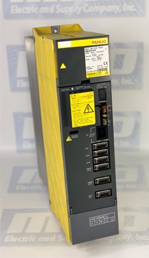
This troubleshooting guide is in reference to Fanuc drives that begin with part number A06B-6079, A06B-6080, and A06B-6096 and is meant to help troubleshoot Fanuc servo amplifiers faults. Before you continue to determine what’s happening to your servo amp, make sure to check for the following:

1 – Determine if your servo amp or motor is defective.

If the alarm is occurring before the motor power is present, consider checking either the servo amp or the feedback circuit. Do this by disconnecting the feedback cable and turning on the power. This will isolate the failure. If you have no alarm, this means the problem lies with the feedback cable or a pulse coder. If the fault remains, the servo amp is the issue.

If the alarm does not occur before motor power, then you will need to continue following the below steps.

If the alarm occurs when motor power is present, the problem might lie with the motor power circuit or the servo amplifier. Disconnect the power cable and turn the machine on. If this action results in the alarm continuing, the problem is with the servo amp. If this action ceases the alarm, follow the next steps.

2 – Shut off the power

Never forget safety when working with these devices. For the proceeding steps, make sure to disconnect the servo amplifier. Also keep in mind, if a drive status alarm appears on the 7 segment display, where the “-” refers to drive not ready (Waiting for an Emergency Stop signal to power up) and “0” refers to drive powering up correctly. Any other number or letter on this status display is one of the FANUC alarm codes. This is one of the more common faults, the FANUC servo Alarm 8.

Here are the steps to check to see what the issue may be when an alarm comes up on your drive.

FANUC Alarm Code 8, 9, or A Steps

1 – Check the link

(A06B-6079 drives only). An A06B-6079 drive can give a fault if the S1 Link is in the wrong position, so check the S1 – JV Connections (Type A Interface) and S2 – JS Connections (Type B Interface). An incorrect setting will cause a FANUC Drive Alarm “8”.

2 – Check the wiring

A L motor is wired in the lower terminals and an M motor is wired in the upper terminals, both as U/V/W/E. JV1B connected from the L command plug of the axis card, JV2B from the M command plug. JX1A connected from previous drive, JX1B connected to the next drive in the line. The last drive in the line has a terminator in JX1B. 24v/0v/ESP connected into CX1A from the previous drive, out of CX1B to the next drive in the line.

3 – Disconnect motor cable

Meggar the motor to check the readings.

4 – Power machine on

Do this while it is in an emergency stop. The drive is faulty if an alarm occurs, expect a “-” reading.

5 – Release Emergency Stop

Power the machine up after releasing the stop. If an alarm occurs, power the machine off and remove motor wires U/V/W/E (Note – this is dangerous on a vertical axis, brake release, slide drops etc). Release Emergency Stop and power the machine up. The drive is faulty if the alarm occurs, expect “0” reading.

Alternative Options

If these steps do not help, an additional test can be performed for equally sized 6079/6080 amplifiers H201 SVM2-12/12          H301 SVM2-12/12/12 H203 SVM2-20/20          H302 SVM3-12/12/20 (L&M) H206 SVM2-40/40          H303 SVM3-12/20/20 (M&N) H208 SVM2-80/80          H304 SVM3-20/20/20 (L/M&N) The suspect axis can be run from the other amplifier in the drive ie X drives M amplifier, Y drives L amplifier. To do this swap round a – X & Y Motor cables U/V/W/E (at the drive) and b – X & Y Command cables (at the drive) (6096 requires parameters changing to swap X & Y round).

The drive is faulty if the alarm remains the same as before the test. For example Alarm “8” is reported on a 6079-H201 drive using JV connections Steps 1~5 above, have been performed and still alarm “8”. Remove the servo motor wires from the lower terminals and reconnect into the upper terminals, upper into lower. Remove JV1B and insert into JV2B, JV2B into JV1B. Retest the machine.

The drive is faulty if the same alarm occurs, ie alarm “8” The fault lies elsewhere on the machine if another alarm occurs, ie alarm “9”. In this example the drive has detected an overcurrent from the L axis, alarm “8” Swapping the cables over allowed a different amplifier to control the axis. An “8” alarm would remain if the same drive circuitry detected the overcurrent. A “9” would occur if the overcurrent was detected using the other drive circuitry in the amplifier and the fault would be caused externally from the drive.

Still having trouble with your Fanuc Servo Alarm 8, 9, or A?

Contact MRO Electric for help. Get yourself a new FANUC servo amplifier or check out our FANUC servo motors. MRO Electric and Supply supplies and repairs a large number of FANUC Servo Drives. To request a quote, please call 800-691-8511 or email sales@mroelectric.com.

Fanuc Spindle Alarms for Troubleshooting

A06B-6079-H106

Alarm # Led Display Content of FANUC SPINDLE Alarms
8 4 2 1

1


o

Motor Overheat

2


o

  Speed deviates from commanded speed

3


o

o

Regenerative fault

6


o

o

  Excess Motor Speed Analog

7


o

o

o

Excess Motor Speed Digital

8

o

      Voltage higher than specified

9

o


o

Radiator for power semiconductor overheat

10

o


o

  +15Volt Supply is low

11

o


o

o

DC Link voltage is high

12

o

o

    DC Link current is high

13

o

o


o

CPU and peripheral parts are defective

14

o

o

o

  ROM is defective

Alarm List for A06B-6044-Hxxx

Alarm List for the following Drives:

Alarm # Led Display Content of Alarms
8 4 2 1

1


o

Motor Overheat

2


o

  Speed deviates from commanded speed

3


o

o

Fuse F7in DC link is blown out.

4


o

    Fuses F1,F2,F3 for AC input blown out.

5


o


o

Fuses AF2 or AF3 on PCB are blown out.

6


o

o

  Excess Motor Speed Analog

7


o

o

o

Excess Motor Speed Digital

8

o

      Voltage higher than specified (24v)

9

o


o

Radiator for power semiconductor overheat

10

o


o

  +15Volt Supply is low

11

o


o

o

DC Link voltage is high

12

o

o

    DC Link current is high

13

o

o


o

CPU and peripheral parts are defective

14

o

o

o

  ROM is defective

15

o

o

o

o

Option circuit fault.

Digital AC Spindle Drive

Alarm List for A06B-6055-Hxxx

Alarm List for the following drives:

  • Model 3 thru 22    A06B-6055-Hxxx


Alarm Display Alarm Content

AL-01

Motor Overheated

AL-02

Speed deviates from commanded speed

AL-03

Fuse F7in DC link is blown out.

AL-04

Fuses F1,F2,F3 for AC input blown out.

AL-06

Excess Motor Speed Analog

AL-07

Excess Motor Speed Digital

AL-08

Voltage higher than specified (24v)

AL-09

Radiator for power semiconductor overheat

AL-10

+15v power supply is abnormally low

AL-11

DC Link voltage is high

AL-12

DC Link current is high

AL-13

Data memory for CPU abnormal

AL-16

RAM in NVRAM is abnormal

AL-17

ROM in NVRAM is abnormal

AL-18

Check sum alarm of ROM

AL-19

Excessive alarm of U phase current detection circuit offset

AL-20

Excessive alarm of V phase current detection circuit offset

AL-21

Excessive alarm of velocity command circuit offset.

AL-22

Excessive alarm of velocity detection circuit offset.

AL-23

Excessive alarm of ER circuit offset.

AL-14

ROM is abnormal

AL-15

Spindle selection control circuit is abnormal.

Alarm List for A06B-6059-Hxxx

Alarm List for the following drives:

  • Model 1S thru 3S   A06B-6059-Hxxx

 View Fanuc Spindle Amp Alarm Codes for Alpha Series here. 

Alarm # Meaning

AL-01

Motor Overheat

AL-02

Speed deviates from commanded speed

AL-03

24v Fuse is blown. (before PCB edition 09A)

AL-04


AL-05


AL-06

Excess Motor Speed Analog

AL-07

Excess Motor Speed Digital

AL-08

Over voltage

AL-09

Overheat of radiator

AL-10

Low voltage of input power.

AL-11

Excessive high voltage of DC link

AL-12

Abnormal current of DC link

AL-13-15


AL-16-23

Defective arithmetic circuit and peripheral circuit

No indication

Defective ROM

Alarm List for A06B-6059-Hxxx

Alarm List for the following drives:

  • Model 6S-26S    A06B-6059-Hxxx
Alarm # Meaning

AL-01

Motor Overheat

AL-02

Speed deviates from commanded speed

AL-03

24v Fuse is blown. (before PCB edition 09A)

AL-04

Open phase of input power.

AL-05


AL-06

Excess Motor Speed Analog

AL-07

Excess Motor Speed Digital

AL-08

Over voltage

AL-09

Overheat of radiator

AL-10

Low voltage of input power.

AL-11

Excessive high voltage of DC link

AL-12

Abnormal current of DC link

AL-13

Defective arithmetic circuit

AL-14

Defective ROM

AL-15

Defective optional circuit.

AL-16-23

Defective arithmetic circuit and peripheral circuit

No indication

Defective ROM

Dealing with FANUC spindle alarms?

Let MRO help you troubleshoot and repair your spindle amplifier, with our professional repair services! Or, if you need a replacement FANUC part, we have you covered with our extensive selection of FANUC parts.

Restoring FANUC Beta Drive Parameters

fanuc robotics

Restoring FANUC Beta Drive Parameters

Some instructions to help out when replacing your drives and restoring the Fanuc beta drive parameters. With Beta series drives the parameters are stored in the drive so if you
replace the drive the parameters will go with it. MRO Electric and Supply maintains a comprehensive stock of new and used FANUC Robotics Drives parts. If you need a replacement part, please call 800-691-8511 or email sales@mroelectric.com.

To save and restore Power Mate CNC Manager parameters to Beta Servo Drives:

This is required when replacing a Beta drive and applies to the following
controls. 16iA,18iA,21iA,16iB,18iB,21iB,20i,16,18,21,0i,Powe rate-iD and Powermate-iH.

1. Make NC PRM 960.3 (PMN) = 0 (Enables PMM function).
2. Select where parameters are to be saved (to save to memory card on i series controls make PRM 960.2
(MD2) = 0 and PRM 960.1 (MD1) = 1, to save as a part program make PRM 960.1 = 0).
3. Set parameter 8760 to the program number you want the parameters to be stored as. Note 1.
4. Press the SYSTEM button then the RIGHT CHAPTER button until the Power Motion Manager screen is displayed.
5. Press the SYSTEM soft key.
6. Press the PARAM soft key.
7. Press the OPRT soft key.
8. Press the RIGHT CHAPTER button. READ and PUNCH soft keys will be displayed.
9. Select EDIT mode.
10.To save parameters from Beta drive to CNC press the READ soft key, press the ALL soft key then the EXEC soft key.
11.To restore the parameters from the CNC to the Beta drive press the PUNCH soft key, press the ALL soft key, then the EXEC soft key.

Be sure to check out our A06B-6105-H002 – FANUC Robotics R-2000iA Servo Amplifier product page to get the best deals.

Unidrive Classic Option Module Trip Codes

unidrive

Unidrive Classic Option Module Trip Codes

On Unidrive Classics, when a UD7x Unidrive option module error trip occurs,
the display will show the trip code as “tr__”. The trip number
can also be read in Unidrive parameter #10.20 or UD70
virtual parameter #88.01, and the line number where the trip
occurs in parameter #17.03, though only if the program was
compiled with debugging information.

When an error occurs in the UD70, the DPL program will
immediately stop. Also, depending on the cause of the trip
and the setting of the Trip enable parameters, the Unidrive will
trip on the “tr__” code. Optionally, an ERROR task may have
been defined which would be executed whenever a run-time
error occurs. MRO Electric and Supply maintains a comprehensive stock of new and used  Control Techniques Unidrive and Control Techniques Unidrive Classic SP parts. If you need a replacement part, please call 800-691-8511 or email sales@mroelectric.com.

Code Description Action
40 Unknown error Always trips
41 Parameter does not exist Trips if #17.14=1
42 Parameter read only Trips if #17.14=1
43 Parameter write only Trips if #17.14=1
44 Parameter value over range Trips if #17.14=1and #17.17=1
45 Virtual access failed – e.g. IOLink not running Trips if #17.14=1 (access)and
#17.15=1* (all time)
46 Stack Overflow Always trips
47 Internal error Always trips
48 Internal error Always trips
49 The wrong system loaded Always trips
50 DPL Maths fault – e.g. divide by zero, overflow etc Trips if #17.14=1
51 DPL array index out of range Trips if #17.14=1
52 User-generated trip from control word Always trips *
53 DPL Program incompatible Always trips
54 DPL Overload – Clock tick too short Trips if #17.14=1
55 RS485 trip – Mode 3 Trips if #17.14=1
56 Option board and system incompatible Always trips
57 Illegal OSCall Always trips
58-59 Internal Error Trips if #17.14=1
60-69 Option generated trip Trips if #17.14=1 *
Prc2 *Watchdog Trip.See the DPL command WDOG for information
Note: The watchdog trip can be disabled by setting #17.18 to 0.
CTTG128.doc V1.0 2 04/12/05

Important Notes:
*When a trip occurs, all tasks of the DPL program will be halted (real-time tasks will
first complete) and any ERROR task is executed. The only exception to this is with trip 45, trip
52, trip 60 with certain option cards, the Watchdog trip (Prc2) and any other normal drive trips.
Other Notes
The line number is only available when the program was compiled with debugging information.
Any other trip numbers that appear are either generated by the drive itself or the DPL program.

Lastly, be sure to check out our article covering Unidrive Security Code Basics here.

Fanuc 911 RAM PARITY ERROR Troubleshooting

Fanuc 911 Error

Fanuc 911 RAM PARITY ERROR Troubleshooting

MRO Electric and Supply maintains a comprehensive stock of new and used FANUC CNC and FANUC Robots parts. If you need a FANUC replacement part, please call 800-691-8511 or email sales@mroelectric.com.

Last week we had a customer who was running an RNC 16 STAR 1990 vintage machine which failed so he decided to replace the main A16B-1010-0280 motherboard. His original problem was that he was receiving a 401 [VRDY Off] Error which then led to a 911 Error. When he replaced the A16B-1010-0280 motherboard, the machine would go directly to the 911 Error.

The first thing we checked for was to make sure that he transferred over all of the EEPROM modules from his original board to the replacement board, which he did. Since that wasn’t the issue, we double checked on the 911 Error, which shows as a RAM PARITY ERROR in the manual. The main cause of this error is an issue with the memory in the unit, which is caused by the memory board failing or losing the parameters in the system.

To check to see if the memory board was causing it or not, you can turn the control off, reset it, and delete the parameters. If this clears the alarm, the control would come up with a different series of servo alarms meaning that the parameters need to be reloaded. If the Fanuc 911 Error comes back it would mean that there is a problem with the memory board which needs to be replaced. Before trying any of this, be sure to confirm that you have all of the parameters saved so you can load them back in. Check out our article on IT and Robotics here.

Once the 911 Error was cleared, the customer was able to load the parameters back on to get the machine up and running.

Troubleshooting Fanuc Servo Devices

A06B-6058-H005

Troubleshooting Fanuc Servo Devices

Recently we had a customer that we helped with troubleshooting a FANUC servo A20B-1003-0090 board that he was installing into an A06B-6058-H005 drive. A handful FANUC troubleshooting options are listed below.

Troubleshooting for the DCAI alarm:

[check items]

  1. Setting S2 for the S series
  2. Machine load
  3. Check connection of separate discharge unit

[Adjustment procedure]

A. Check amplifier setting S2. If the setting is incorrect, go to Cause 1. If the setting is correct, go to A-0.

A-0: Check whether a separate discharge unit is being used. If it is being used, go to A-1. If not being used, go to A-2.

A-1: Check the connection of the separate discharge unit. If the connection is incorrect, go to Cause 2. If connection is correct, go to A-2.

A-2: Check the acceleration/deceleration frequency. If the frequency is too high, go to Cause 3. If the frequency is low enough, go to A-3.

A-3: Replace the servo amplifier. If a DCAL alarm no longer occurs, go to Cause 4. If a DCAL alarm still occurs, go to Cause 3.

[Causes]

1). If the setting S2 of the S series servo amplifier is incorrect, a DC alarm is caused.

2). If the separate discharge unit is connected incorrectly, a DC alarm occurs.

3). Compared to the regenerative power of the amplifier, the regenerative energy of the motor is too large. (The inertia is too large or the acceleration/deceleration frequency is too high.) In this case, try to decrease the acceleration/deceleration frequency or install a separate discharge unit.

4). The discharge transistor (Q1) in the servo amplifier is defective.

MRO Electric and Supply has new and refurbished FANUC CNC products available, including FANUC Servo parts. We also offer repair pricing. For more information, please call 800-691-8511 or email sales@mroelectric.com.

Rebuild a Fanuc Motor – Model A06B-0131-B075 Process

Gallery of pictures showing the process that it takes to rebuild a Fanuc motor, part number A06B-0128-B675#7008.

Original pictures of the motor. Fan is dirty, all sides show significant use.

fanuc motor repair
fanuc motor repair

Upon disassembling the FANUC servo motor, the residue was found in the stator prompting the removal of the motor shaft. This would have caused a short in the stator once running.

The finished product, after the motor is rebuilt and fully tested.

rebuild a fanuc motor
fanuc servo motor repair

MRO Electric stocks new and refurbished FANUC CNC Motors. We also provide pre-priced Control Techniques repairs. For more information or to request a quote, please call 800-691-8511 or email sales@mroelectric.com.