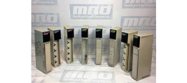
The following is a list of instructions for installing the these Spindle Drives with the A16B-1100-0200 Spindle Drive PCB:
- A06B-6059-H001
- A06B-6059-H002
- A06B-6059-H003
- A06B-6059-H004
And these Spindle Drives with the A16B-1100-0241 Spindle Drive PCB:
- A06B-6060-H001
- A06B-6060-H002
- A06B-6060-H003
- A06B-6060-H004
- A06B-6060-H005
- A06B-6060-H006
- A06B-6060-H007

Instructions:
- Make sure the jumpers on the new spindle PCB match the jumpers on your old spindle PCB.
- Remove the software chips from the old spindle PCB and install them onto the new spindle PCB.
- If possible, remove the NVRAM chip from the old spindle PCB and install it onto the new spindle PCB. This way you will not have to reprogram the chip as the new spindle will have the same instructions as the previous one.
It is very important to follow the manual and make sure that the chips and cards you are moving around are installed correctly. For instance, if you were to incorrectly install the software chips, not only would the display not show anything, you are leaving open the possibilities for a short and causing yourself even more trouble.
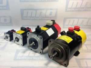
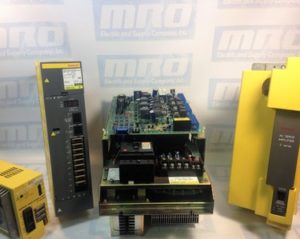
Sometimes you may not have the necessary equipment to make a diagnosis on your motor, but we do. MRO Electric and Supply offers high quality repair services on all motors and spindle drives so you don’t have to worry about it. Please take a look at our website to see all available brands and parts we can service for you. Our rebuilds for these size drives usually only take 2-3 days, which includes rebuilding the part, painting the part, and fully testing the part to ensure top quality. By getting your part back to you as soon as possible, you are able to minimize downtime, and by doing the job right you can have peace of mind knowing that your FANUC drive will now work properly and not be the reason for downtime in the future.
MRO Electric and Supply has new and refurbished FANUC CNC parts available. For more information, please call 800-691-8511 or email sales@mroelectric.com.