Control Techniques Commander CDE Trips: Troubleshooting

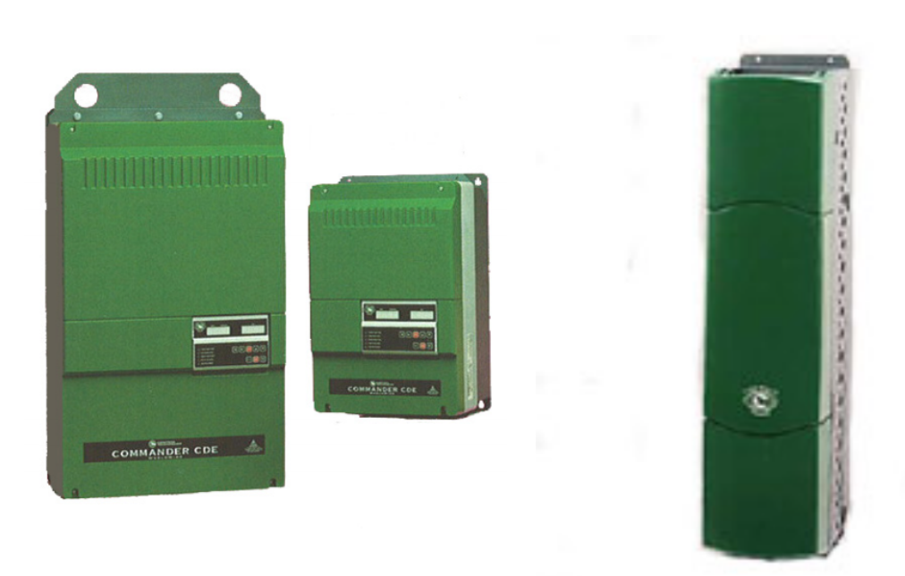
CDE TRIPS ( MEDIUM / LARGE AND HPCDE )
Control Techniques Commander CDE Trips: Troubleshooting

MRO Electric and Supply has new and refurbished Control Techniques parts available now, and also offers repair pricing. For more information, please call 800-691-8511 or email sales@mroelectric.com.

Control Techniques Commander CDE Trips: Troubleshooting

When a failure occurs with the CDE drive the display will flash a series of segment characters for the trip.

Example: tr iP OU

Commander CDE series stores the past ten failure codes in parameters #10.14 – 10.23 in trip number form. A numeric value trip code is a basic form of the symptom for the technician to work with. These past trips can be accessed via the keypad by entering the value of 149 in the keypad at parameter 00.

Scroll to menu 10, for parameter #10.14 to see a trip number.

Example: 6

Symptom explanations provide an avenue on how to analyze the drive for particular problems.

To make the troubleshooting process easier a chart was created to link the type of trip with the symptom.

TRIP Display | TRIP Number | Symptom

cL 114-20m Loop of current loop 1
Et2External trip contact has opened
I . t3Overload lxt- Sustained Overcurrent
Oh4Heatsink over temperature- Fan Failure ???
OI AC5Instantaneous AC over current trip
OU6DC bus over voltage-Braking Resistor Problem
Ph7AC Supply phase loss
PS8Internal power supply fault
th9Motor thermistor trip-Hot Motor
OI dC10Instantaneous DC over current trip
EPS11External power supply fault +24vdc short?
th512Motor thermistor short circuit
UU13DC bus under voltage
SCL14Serial comms. Loss-Keypad loose/failure
POdL15Loss of Control keypad
cL2164-20mA Loop Loss of current loop 2
cL3174-20mA Loop Loss of current loop 3
EEF18EEPROM
Prc219Processor 2 fault
OA20Ambient over temperature
rS21Stator resistance measurement failure
OUSP22Overspeed Trip
hFPP26-39Hardware Fault
PhPC100AC Supply phase loss from a drive module
OtPC101Over temperature trip in a Drive module
OtPn102-109Over temperature trip in Drive Module #n
PSPn110-117Over voltage trip in Drive Module #n
I OPn118-125Instantaneous Over current in Drive #n
OuPn126-133Over voltage trip in Drive Module #n
dcPn134-141Instantaneous DC current trip in Drive #n
FtYP142Spurious Unidentified trip
ConF143Module Address switches incorrect
8.8.8.8.-I x t trip Warning flashing dots

Control Techniques Commander SK Security Features

The Control Techniques Commander SK series contains several levels of security.  The level 1 security set has parameters from 1 – 10.  These parameters are the most basic drive configuration registers, containing mostly motor information and start/stop selections.  Level 2 allows you to view and modify parameters 1 – 60.  These include more advanced features, such as, the brake control and fieldbus configuration.  Level 3 access is used to access parameter 1 – 95.  Parameters 61 – 80 in this level can be used to gain access to any register in the drive.  Within level 3 you are also able to gain access to the diagnostic functions of Pr 81 – Pr 95.  The last level is a custom security setting called Loc which can be used to edit any registers in the drive. Check out our website for all of our Commander SK series troubleshooting documentation.

Read More

Control Techniques Unidrive Option and Solution Modules

Unidrive Option Modules

The Control Techniques Unidrive Option and Solution Modules will enhance the functionality of your variable speed drives, allowing them to consistently run at peak performance. The modules will easily integrate with your existing automation system.  A high speed parallel bus is used between the drive and the module which helps remove delays and will improve the drives reaction time.

The options offered by Control Techniques can be categorized by the following:

  • Intelligence and Safety – offering programmable automation and motion option modules
  • Communication – offering Ethernet and fieldbus communications option modules
  • Feedback – offering encoder and resolver option modules
  • Inputs and Outputs – offering additional analog and digital input and output option modules

Read More

Control Techniques Commander SE HF Trip Codes

Commander SE
Commander SE

The Control Techniques Commander SE Microdrive series is an AC open loop vector that provides great flexibility as well as a small footprint.  Although this series is reliable you may encounter one of the HF Trip codes listed below.  These codes are a result of an internal error in the drive.  Most often these trip codes can be resolved by powering down and allowing the drive sit for 5 minutes before powering up again.

If the HF Fault code does not clear then your drive will likely require a repair.

Read More

Emerson Commander SK Advanced User Guide & Manual

Struggling with troubleshooting and repair? Keep your equipment running smoothly by using the following guide to diagnose any trip codes. The following are some of the common errors you might encounter:

Emerson Commander SK Fault & Trip Codes by Control Techniques

Trip Code Condition Possible Cause
UU DC Bus under voltage Low AC Supply Voltage

Low DC Bus voltage when supplied by an external DC power supply

OU DC Bus over voltage Deceleration rate set too fast for the inertia of the machine

Mechanical load driving the motor

OI.AC** Drive output instantaneous over current Insufficient ramp times

Phase to phase or phase to ground short circuit on the drives output

Drive requires autotuning to the motor

Motor or motor connections changed, re-autotune drive to motor

OI.br** Braking Resistor instantaneous over current Excessive current in braking resistor

Braking resistor value to small

O.SPd Over Speed Excessive motor speed (typically caused by a mechanical load driving the motor
tunE Autotune stopped before completion Run command removed before autotune compelte
It.br I2t on Braking Resistor Excessive braking resistor energy
lt.AC l2t on drive output current Excessive Mechanical load

High impedance phase to phase or phase to ground short circuit at drive output

Drive requires re-autotuning to motor

O.ht1 IGBT over heat based on dries thermal model Over heat software thermal module
O.ht2 Over heat based on drives heatsink Heatsink temperature exceeds maximum allowable
th Motor thermistor trip Excessive motor temperature
O.Ld1* User +24v or digital output overload Excessive load or short circuit on +24v output
cL1 Analogue input 1 current mode, current loss Input current less than 3mA when 4-20 or 20-4mA modes selected
SCL Serial communication loss time-out Loss of communication when drive is under remote control
EEF Internal Drive EEPROM trip Possible loss of parameter values
PH Input phase imbalance or input phase loss One of the input phases has become disconnected from the drive (applies to 200/400v three phase drives only, not dual rated drives.
rS Failure to measure motors stator resistance Motor too small for drive

Motor cable disconnected during measurement

C.Err SmartStick data error Bad connection or memory corrupt within SmartStick
C.dAt SmartStick data does not exist New/empty SmartStick being read
C.Acc SmartStick read/write error fail Bad connection or faulty SmartStick
C.rtg SmartStick/drive rating change Already programmed SmartStick read by a drive of a different rating
O.cL Overload on current loop input Input current exceeds 25mA
HFxx trip Hardware faults Internal drive hardware fault

HF01 to HF03
Not used
HF04
Low DC bus at power up- may indicate an AC Input or pre-charge problem
HF05
No internal handshake signal from second processor (DSP) at start up
HF06
Unexpected interrupt
HF07
Watchdog failure
HF08
Interrupt crash (code overrun)
HF09 to HF10
Not used
HF11
Access to the EEPROM failed- tried to read stored parameter data but failed
HF12 to HF19
Not used
HF20
Power stage – code error Tried to read power board and read back erroneous
HF21
Power stage – unrecognized frame size
HF22
Overcurrent detection at power up- possible output short or bridge failure
HF23
DSP software overrun
HF24
Not Used
HF25
DSP Communications failure- communication from main to 2nd processor
HF26
Soft start relay failed to close; or soft start monitor failed; or braking
IGBT short circuit at power up
HF27
Power stage thermistor fault
HF28
Power circuit thermistor 2 or 3 fault Internal fan fault on size 3 only
HF29
Fan failure (current too high – only on drives with a fan) see note below
HF30
Not used
HF31
Internal Cap Bank Fan failure- check for fan rotation/blockage Size 4 and up
HF32
Power circuit temperature feedback multiplexer failure

Looking for more information about Control Techniques equipment? Read on here. 

Shopping for new or refurbished Control Techniques parts? Shop for the parts you’re looking for here, or find out more about how MRO Electric can help you repair your equipment

Experiencing Trip Codes on Your Commander SK?

Trip codes can be puzzling, but MRO Electric has the solution. Whether you need in-depth guides to understand your Commander SK drive’s codes or require immediate repair service, we’re here to support you in restoring your system’s efficiency swiftly.