tsxcusbmbp

Schneider Electric TSXCUSBMBP: Beyond the User Manual

Need a replacement TSXCUSBMBP? Request a Price Quote Now.

The Schneider Electric TSXCUSBMBP is a USB Modbus Plus Communications Adapter. In this guide, we will show you how to install the hardware, configure the driver software, and use the Modbus Plus network diagnostics features of the driver software.

Important: The least versions of the TSXCUSBMBP driver to run on Win Server 2012 R2 are driver versions 8.0 and 8.1.

The TSXCUSBMBP is designed to bridge the gap between a USB connection and the Modbus Plus network. It combines hardware and software together in one simple and single device. The module has its own Modbus Plus node address which can be set through the TSXCUSBMBP driver software. This module allows software applications using the serial Modbus RTU communications to connect on the high-speed Modbus Plus network, as well as provide diagnostic capabilities to the Modbus Plus network.

Most Win32 Applications that support serial Mdubus communications can use a Modicon TSXCUSBMBP to connect on a Modbus Plus network. A VSP (Virtual Serial Port) is what redirects communications from Concept, Unity, ProWorx32 and other programs to the TSXCUSBMBP communications adapter. After the VSP is installed, it will create one serial port with the port reference as defined in the module’s driver software. When configuring the Modbus application software, this port reference is selected as the serial port for the application to use. The routing table is used to associate Modbus Slave IDs with 5-byte Modbus Plus routing paths which allow the application software to communicate with any Modbus Plus device within range on the network.

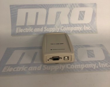
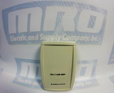
The TSXCUSBMBP’s hardware consists of a box with a USB cable from one end (which connects to the PC) and a standard Modbus Plus DB9 connector on the other end (for the Modbus Plus network). Local signalling LEDs on the top cover of the device tell you the presence of power from the USB port and the state of the Modbus Plus network – no external power supply is required.

TSXCUSBMBP Installation

To install the TSXCUSBMBP, you will need the following:
– Windows XP Operating System with service pack 2, or Windows 2000 with Service Pack 4 or greater.
– 1 MB of free disk space.
– Minimum of 256 MB of RAM.
– One free USB port or a USB Hub that supports USB 1.1 or greater.

If a previous version of the TSXCUSBMBP was installed, the VSP component of the driver must be manually uninstalled using Device Manager before a new version can be installed. After this, the new driver should be installed before connecting the new TSXCUSBMBP to the PC. After the new driver is installed, connect the TSXCUSBMBP and install using the New Hardware Wizard. After completing the instructions, you should see a message stating “Your new hardware is ready to use.” Restart your computer, and the device should be fully functional. If the driver starts up before the TSXCUSBMBP is connected, then it will be necessary to re-scan for adapters so the driver can detect it.

TSXCUSBMBP Configuration

To configure the module, you will need to do the following:

1. Configure the Modbus Plus Node Address
The communications adapter must be assigned a Modbus Plus node address to communicate on the network. Select “Settings” and then type the address in the appropriate box. When complete, hit “Save”.

2. Configure the Slave Response Timeout
The slave response timeout is used by the module each time it sends a request from an application out on the network to a slave device. Use the manual to determine the appropriate value that should be used with your system. Select “Settings” and then type the value in the appropriate box. When complete, hit “Save”.

3. Configure the Virtual Serial (COM) Port
To do this, select “Virtual Modbus Port.” Select the desired COM port from the list available. When complete, click “Save”.

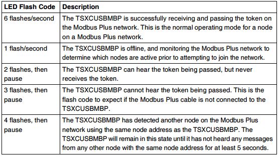
If you experience any problems while configuring your adapter, please use the table below to determine the appropriate error code given by the LEDs, if applicable. As always, refer to the user manual for more complete information.

TSXCUSBMBP Error Codes
MRO Electric carries both New and Refurbished TSXCUSBMBP Communication Adapters. For more information on this module or to request a price quote, please call 800-691-8511 or email sales@mroelectric.com.

Enhance System Performance with Modicon Quantum I/O Modules

Substation I/O modules for direct 125 Vdc control
Quantum I/O modules are available for direct connection to critical 125 Vdc battery powered equipment such as circuit breakers, protective relays, transformers and capacitor banks.

  • Built-in high transient noise immunity ensures reliable operation in harsh 125 V DC environments.
  • The 125 Vdc 30A high current output module eliminates expensive high current interposing relays used in breaker tripping and closure.
  • The solid-state 125 Vdc low current output module ensures long life and trouble-free operation in higher frequency 125 Vdc switching environments without the use of expensive external snubbing circuitry.
  • Over-current/ short circuit diagnostics and protection on all solid state 125 Vdc outputs reduce downtime by ensuring quick identifi- cation of circuit prob- lems and fast repair.

Latch/Interrupt module for time critical applications
The Quantum Latch/ Interrupt module is a multi-purpose high speed input, latch,
and interrupt module combined, which is configurable through programming software. Interrupt handling instructions are part of the 984 Ladder Logic instruction set. Quantum throughput performance for 2 interrupts is typically 1ms.
High speed counters don’t miss a pulse
Quantum high speed counter modules, such as the 140EHC10500, have the ability to count pulses at speeds much faster than the Quantum controller can directly do by itself. These modules automatically report the current count to the Quantum controller every scan.

Simple ASCII exchanges
The Quantum ASCII module is a general purpose ASCII interface that provides the ability to communicate and ex- change data with devices including printers, bar code readers and scanners, weigh scales, and meters. This module is designed for relatively simple point to point ASCII communications, with ASCII messages stored inside the module triggered by logic within the Quantum controller.

TSX PLCs – Compact, Flexible, Cost-Effective

TSX PLCs
TSX Nano PLCs are easy to set up and have numerous built in functions, such as memory for storing programs, battery-backed RAM, and real-time clocks for modules with 16 and 24 I/O’s. They can be installed easily on a mounting rail or base plate in the vertical or horizontal position. TSX PLCs are programmed in lists of instructions using the FTX 117 programming terminal, in Ladder or Instruction list language using software on an FT 2000, FTX 517 terminal or PC compatible. They can be used to augment extendable TSX PLCs using a single extension per base. Depending on the model they have

16 I/O : 9 inputs + 7 outputs
24 I/O : 14 inputs +10 outputs.

The following types of inputs and outputs are used:

Inputs : 24 Volts
Outputs : Relay outputs for models with ~ 100… 240 Volt power supply, transistor outputs with positive logic for models with 24 Volt power supply.

I/O Extension

Each TSX Nano base PLC can be extended using an I/O extension. This extension is created by one of the PLCs with 10, 16, or 24 i/o. The function of each PLC is defined by the position of the coding selector switch:
Position 0 : base PLC
Position 1 : I/O extension

Peer PLCs

Up to 3 peer TSX PLCs, communicating via common words, can be connected to the base PLC. In this case, only the base PLC can receieve an I/O extension. The function of each PLC is defined by the position of the coding selector switch. I/O addressing of peer PLCs is identical to that of the base TSX PLC. The extension link cable between the base PLC and PLC extensions is shielded, twisted pair  and is no more than 200 meters long.  Each PLC has 2 reserved (IW) and 2 reserved (QW) words for exchanging data between PLCs. These exchange words are updated automatically. For each PLC, the user program is only able to write to the 2 %QW output words and read the 2 %IW input words.

MRO has many Modicon PLCs available. For more information, please email sales@mroelectric.com or call 1-800-691-8511.

Siemens Sinumerik Drive and I/O Alarms

For troubleshooting your Siemens Sinumerik system, here is a list of the Siemens Sinumerik Drive and I/O Alarms directly from the Sinumerik manual. For more info, give us a call at 800-691-8511 or email sales@mroelectric. Our full Sinumerik series is listed here.

Drive and I/O alarms

Alarms

334 Diagnostics Manual, 03/2011, 6FC5398-2CP10-3BA0

300411 Axis %1 drive %2 error when reading a file (%3, %4)

Parameters: %1 = NC axis number

%2 = Drive number

%3 = Error code 1

%4 = Error code 2
Read More

Modicon Quantum Overview: Power Supplies, CPUs, I/O Modules

The Modicon Quantum system is a special purpose computing system with digital processing capabilities. Modicon Quantum is designed for real-time control in industrial and manufacturing applications in a module, expandable architecture employing the following modules.

–          Power Supply

–          CPU

–          I/O

–          I/O Network Interface

–          Intelligent/Special Purpose I/O

–          Simulator (XSM)

–          Battery

–          Backplanes

–          CableFast Cabling

Quantum Power Supplies are used to supply system power to all modules inserted into the backplane, including CPU modules, Interface modules, and I/O modules. Depending upon the system configuration, the option exists of using the power supply in three different modes. The three modes are:

–          Standalone: For 3A, 8A, or 11A configurations that do not require fault tolerant or redundant capabilities.

–          Standalone Summable: For configurations consuming more than the rated current of one supply, two summing power supplies can be installed on the same backplane.

–          Redundant: For configurations requiring power for uninterrupted system operation. Two redundant power supplies are required for redundancy.

The Quantum CPU is a module residing on the Quantum local I/O backplane. The CPU is a digitally operating electronic system, which uses a programmable memory for the internal storage of user interactions. These instructions are used to implement specific functions such as logic, process sequencing, timing, coupling, and arithmetic. These instructions allow control through digital and analog outputs, for various types of machines and processes.  The Quantum CPU serves as a bus master controlling the local, remote, and distributed I/O of the Quantum system.

Quantum I/O modules are electrical signal converters that convert signals to and from field devices to a signal level and format, which can be processed by the CPU such as limit switches, proximity switches, temperature sensors, solenoids, and valve actuators. All I/O modules are optically isolated to the bus, ensuring safe and trouble-free operation. All I/O modules are also software configurable.

MRO Electric and Supply has new and refurbished Modicon Quantum products available. We also offer repair pricing. For more information, please call 800-691-8511 or email sales@mroelectric.com.

Real-Time Data Collection using PLC Networking

This article from Control Engineering offers a great preview of the future of manufacturing with PLCs. Ethernet connections allow for real-time data collection, which introduces great networking potential between workers and the machines. Because PLCs can be programmed to make decisions based on input variables, we can automate more tasks but still be confident that process variables are under control. The development and innovation of Modicon Quantum I/O Modules create the backbone of the PLC networking configuration.

Another exciting revelation in the article:

To meet the growing operation needs of industrial automation, networks continue to expand, offering monitoring and control capabilities in areas not previously possible. Device networks are now using fieldbus-to-Ethernet integration to develop enterprise-wide control networks. Merging networking functionality with PLCs enables users to off-load main processor tasks for distributed control in the field, placing control-level devices closer to the action. Additionally, by combining control with distributed I/O, manufacturers can lower their total cost of operation by streamlining data acquisition, communication, and factory-wide connectivity.

We can’t wait to see how users pair the networking capabilities of PLCs with infrastructure already in place on the factory floor.

MRO Electric and Supply has new and refurbished Modicon products available including the Modicon Quantum series. We also offer repair pricing. For more information, please call 800-691-8511 or email sales@mroelectric.com.