Instructions for Installing a 6055 Spindle Drive to A20B-1001-0120

The following is a list of instructions for installing a 6055 Spindle Drive with the A20B-1001-0120 Spindle Drive PCB:

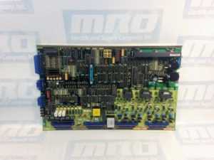
A20B-1001-0120

Instructions:

  1. Make sure the jumpers on the new spindle PCB match the jumpers on your old spindle PCB.
  2. Remove the software chips from the old spindle PCB and install them onto the new spindle PCB.
  3. If possible, remove the NVRAM chip from the old spindle PCB and install it onto the new spindle PCB. This way you will not have to reprogram the chip as the new spindle will have the same instructions as the previous one.
  4. If possible, remove the DAC chip from the old spindle PCB and install is onto the new PCB. There may not be a DAC chip on your previous board and if that is the case do not worry about it. However if the old board does have the chip, failure to install it correctly into the new board will cause issues.
  5. Make sure to set the 200/230 voltage switch to the same setting it is on the old board. This switch also may not be on all drives.

It is very important to follow the manual and make sure that the chips and cards you are moving around are installed correctly. For instance, if you were to incorrectly install the software chips, not only would the display not show anything, you are leaving open the possibilities for a short and causing yourself even more trouble.

Sometimes you may not have the necessary equipment to make a diagnosis on your motor, but we do. MRO Electric and Supply offers high quality repair services on all motors and spindle drives so you don’t have to worry about it. Please take a look at our website to see all available brands and parts we can service for you. Our rebuilds for these size drives usually only take 2-3 days, which includes rebuilding the part, painting the part, and fully testing the part to ensure top quality. By getting your part back to you as soon as possible, you are able to minimize downtime, and by doing the job right you can have peace of mind knowing that your FANUC drive will now work properly and not be the reason for downtime in the future.

MRO Electric and Supply has new and refurbished FANUC CNC parts available. For more information, please call 800-691-8511 or email sales@mroelectric.com.

Instructions for Installing PCB to A06B-6052-H001/4 and more

The following is a list of instructions for installing the these Spindle Drives:

With the A16B-1100-0080 Spindle Drive PCB.

This guide covers the same installation procedure for the following parts:

spindle drive pcb

Instructions:

  1. Make sure the jumpers on the new spindle PCB match the jumpers on your old spindle PCB.
  2. Check to see the status of the 200/230 voltage switch on the old spindle PCB and set it to the same setting on the new spindle drive. You can locate the switch underneath the lid on smaller drives.
  3. Remove the software chip on the old spindle drive and install it into the new one.
  4. If you used a DAC chip in your old spindle, you can can remove it from your old spindle PCB and install it into your new one.

It is very important to follow the manual and make sure that the chips and cards you are moving around are installed correctly. For instance, if you were to incorrectly install the software chips, not only would the display not show anything, you are leaving open the possibilities for a short and causing yourself even more trouble.

Sometimes you may not have the necessary equipment to make a diagnosis on your motor, but we do. MRO Electric and Supply offers high quality repair services on all motors and spindle drives so you don’t have to worry about it. Please take a look at our website to see all available brands and parts we can service for you. Our rebuilds for these size drives usually only take 2-3 days, which includes rebuilding the part, painting the part, and fully testing the part to ensure top quality. By getting your part back to you as soon as possible, you are able to minimize downtime, and by doing the job right you can have peace of mind knowing that your FANUC drive will now work properly and not be the reason for downtime in the future.

MRO Electric and Supply has new and refurbished FANUC CNC parts available. For more information, please call 800-691-8511 or email sales@mroelectric.com.

Instructions for Installing PCB to A06B-6059-H001/4 and A06B-6060-H001/7 Spindle Drives

The following is a list of instructions for installing the these Spindle Drives with the A16B-1100-0200 Spindle Drive PCB:

And these Spindle Drives with the A16B-1100-0241 Spindle Drive PCB:

  • A06B-6060-H001
  • A06B-6060-H002
  • A06B-6060-H003
  • A06B-6060-H004
  • A06B-6060-H005
  • A06B-6060-H006
  • A06B-6060-H007

fanuc cnc

Instructions:

  1. Make sure the jumpers on the new spindle PCB match the jumpers on your old spindle PCB.
  2. Remove the software chips from the old spindle PCB and install them onto the new spindle PCB.
  3. If possible, remove the NVRAM chip from the old spindle PCB and install it onto the new spindle PCB. This way you will not have to reprogram the chip as the new spindle will have the same instructions as the previous one.

It is very important to follow the manual and make sure that the chips and cards you are moving around are installed correctly. For instance, if you were to incorrectly install the software chips, not only would the display not show anything, you are leaving open the possibilities for a short and causing yourself even more trouble.

Sometimes you may not have the necessary equipment to make a diagnosis on your motor, but we do. MRO Electric and Supply offers high quality repair services on all motors and spindle drives so you don’t have to worry about it. Please take a look at our website to see all available brands and parts we can service for you. Our rebuilds for these size drives usually only take 2-3 days, which includes rebuilding the part, painting the part, and fully testing the part to ensure top quality. By getting your part back to you as soon as possible, you are able to minimize downtime, and by doing the job right you can have peace of mind knowing that your FANUC drive will now work properly and not be the reason for downtime in the future.

MRO Electric and Supply has new and refurbished FANUC CNC parts available. For more information, please call 800-691-8511 or email sales@mroelectric.com.

Setting the Sensor Gap on your Fanuc Spindle Motor

Today we will be helping you with your installation of a spindle motor. Alarms are caused by tensions issues with the belt – either being too tight or too loose in relation to the sensor. MRO Electric and Supply offers both new and refurbished FANUC Spindle amps, troubleshooting on our blog for a wide variety of parts, and repair services on any product we offer.

Steps for fixing the sensor gap

  1. Disconnect the wiring inside of the terminal box.
  2. Next take out the 4 bolts that hold the shroud/fan to the motor.
  3. Remove the screws from the cover of the sensor on the motor.
  4.  Loosen the screws holding the sensor in place until you have enough room to be able to slide a piece of paper between the gear and sensor.
  5. Tighten the 2 screws that hold the sensor in place to make sure they do not rub against each other at all.
  6. Fasten the sensor cover back to the sensor and tighten accordingly.
  7. Reattach the shroud and the fan to the motor.
  8. Configure the wiring back to what it was originally.

fanuc cnc

Now that the sensor for your FANUC Spindle amp is corrected, it should work properly. If you are still having issues we recommend looking throughout our blog as we have many articles based on helping the user troubleshoot any and all issues with their motor.

Sometimes you may not have the necessary equipment to make a diagnosis on your motor, but we do. MRO Electric and Supply offers high quality repair services on all motors so you don’t have to worry about it. Please take a look at our website to see all available brands and parts we can service for you.

MRO Electric and Supply has new and refurbished FANUC CNC parts available. For more information, please call 800-691-8511 or email sales@mroelectric.com.

FANUC 18i M-Codes

Fanuc Motors

In the world of automation, whether we’re talking about factory or shop automation, understanding how to operate and maintain FANUC CNC parts is imperative. Several businesses and companies suffer from dreaded downtime because a team isn’t well-rounded; many team members may know how to manage machine operators, etc., but are unaware of how to operate a CNC themselves. For a manager, knowing and understanding exactly what to look for to avoid an operating issue starts with understanding the basics of CNC machining and programming.

CNCs originally started coming about in the late 1940s, not long after World War II as NCs (Numerical Controls). They were engineered to be a reliable, cost-effective way to manufacture and design an increased amount of parts for the aircraft industry. Based on already-existing modified tools equipped with motors that manipulated the controls, CNCs were quickly and abruptly built up with computers, both digital and analog. As time has gone on, CNCs have continued to evolve as technology evolves.

Early Numerical Controls initially lacked computers. They also lacked calculating ability, which is absolutely unheard of in today’s world. After the 1960s, numerical controls eventually gained calculating and computer functions. Onboard processing became feasible and, as a result, CNC machines came about. Via the initiation of CNCs, a handful of features were then attainable, fortunately, including canned cycles, tool length compensation, sub programming, radial compensation and tool diameter.

Preparatory Codes

NC and CNC G Codes are referred to as preparatory codes. By preparing the machine to perform a specific function like, for example, rapid travel G0 / G00, the preparatory process is important to understand, as all of the stages of production are.

Miscellaneous Codes

NC / CNC M codes are known as miscellaneous codes.  CNC M codes basically perform on and off functions such as:

  • stopping processing of CNC code M0 / M00
  • turning the spindle on M3 / M0 or M3 / M03
  • stopping the spindle M5 / M05
  • turning coolant on M8 / M08

MRO Electric and Supply has new and refurbished FANUC CNC parts available. We also offer repair pricing. For more information, please call 800-691-8511 or email sales@mroelectric.com.

G Code and M Code

The ANSI standard for G code and M code programming is ANSI/EIA 274D-1988. The ISO standard for G code and M code programming is ISO 6983. There is a new and different standard ISO 14649 also known as the STEP-NC standard that addresses NC and CNC programming using the enhanced features of CAD and/or CAM software.

Machine tool builders are not required to adhere to standards and every so often create variations to standard G codes and M codes. Occasionally design different, unique alternatives to orthodox G codes and M codes. Typically, the majority of CNC G codes are considered modal, which means they stay active until they’re changed. Along with understanding CNC codes, feel free to view another one of our articles focused on choosing a CNC to become as well-versed with CNCs as possible.

Auxiliary Function (M Function)

When a numeral is specified following address M, code signal and a strobe signal are sent to the machine. The machine uses these signals to turn on or off its functions. Usually, only one M code can be specified in one block.

In some cases, however, up to three M codes can be specified for some types of machine tools. Which M code corresponds to which machine function is determined by the machine tool builder.

The machine processes all operations specified by M codes except those specified by M98, M99,M198 or called subprogram(Parameter No.6071 to 6079), or called custom macro (Parameter No.6080 to 6089). Refer to the machine tool builder’s instruction manual for details.

The following M codes have special meanings:
  • M02, M03 (End of Program)
    • This indicates the end of the main program Automatic operation is stopped and the CNC unit is reset.
    • This differs with the machine tool builder. After a block specifying the end of the program is executed, control returns to the start of the program. Bit 5 of parameter 3404 (M02) or bit 4 of parameter 3404 (M30) can be used to disable M02, M30 from returning control to the start of the program.
  • M00 (Program Stop)
    • Automatic operation is stopped after a block containing M00 is executed. When the program is stopped, all existing modal information remains unchanged. The automatic operation can be restarted by actuating the cycle operation. This differs with the machine tool builder.
  • M01 (Optional Stop)
    • Similarly to M00, automatic operation is stopped after a block containing M01 is executed. This code is only effective when the Optional Stop switch on the machine operator’s panel has been pressed.
  • M98 (Calling of Sub-Program)
    • This code is used to call a subprogram. The code and strobe signals are not sent.
  • M99 (End of Subprogram)
    • This code indicates the end of a subprogram. M99 execution returns control to the main program. The code and strobe signals are not sent.
  • M198 (Calling a Subprogram)
    • This code is used to call a subprogram of a file in the external input/output function. See the description of the subprogram call function (III–4.7) for details.
Multiple M Commands in a Single Block

In general, only one M code can be specified in a block. However, up to three M codes can be specified at once in a block by setting bit 7 (M3B) of parameter No. 3404 to 1. Up to three M codes specified in a block are simultaneously output to the machine. This means that compared with the conventional method of a single M command in a single block, a shorter cycle time can be realized in machining.

CNC allows up to three M codes to be specified in one block. However, some M codes cannot be specified at the same time due to mechanical operation restrictions. For detailed information about the mechanical operation restrictions on simultaneous specification of multiple M codes in one block, refer to the manual of each machine tool builder. M00, M01, M02, M30, M98, M99, or M198 must not be specified together with another M code. Some M codes other than M00, M01, M02, M30, M98, M99, and M198 cannot be specified together with other M codes; each of those M codes must be specified in a single block.

Such M codes include these which direct the CNC to perform internal operations in addition to sending the M codes themselves to the machine. To be specified, such M codes are M codes for calling program numbers 9001 to 9009 and M codes for disabling advance reading (buffering) of subsequent blocks. Meanwhile, multiple of M codes that direct the CNC only to send the M codes themselves (without performing internal operations ) can be specified in a single block.

M Code Group Check Function

The M code group check function checks if a combination of multiple M codes (up to three M codes) contained in a block is correct.

This function has two purposes. One is to detect if any of the multiple M codes specified in a block include an M code that must be specified alone. The other purpose is to detect if any of the multiple M codes specified in a block include M codes that belong to the same group. In either of these cases, P/S alarm No. 5016 is issued. For details on group data setting, refer to the manual available from the machine tool builder.

  • M Code Setting
    • Up to 500 M codes can be specified. In general, M0 to M99 are always specified. M codes from M100 and up are optional.
  • Group Numbers
    • Group numbers can be set from 0 to 127. Note, however, that 0 and 1 have special meanings. Group number 0 represents M codes that need not be checked. Group number 1 represents M codes that must be specified alone.
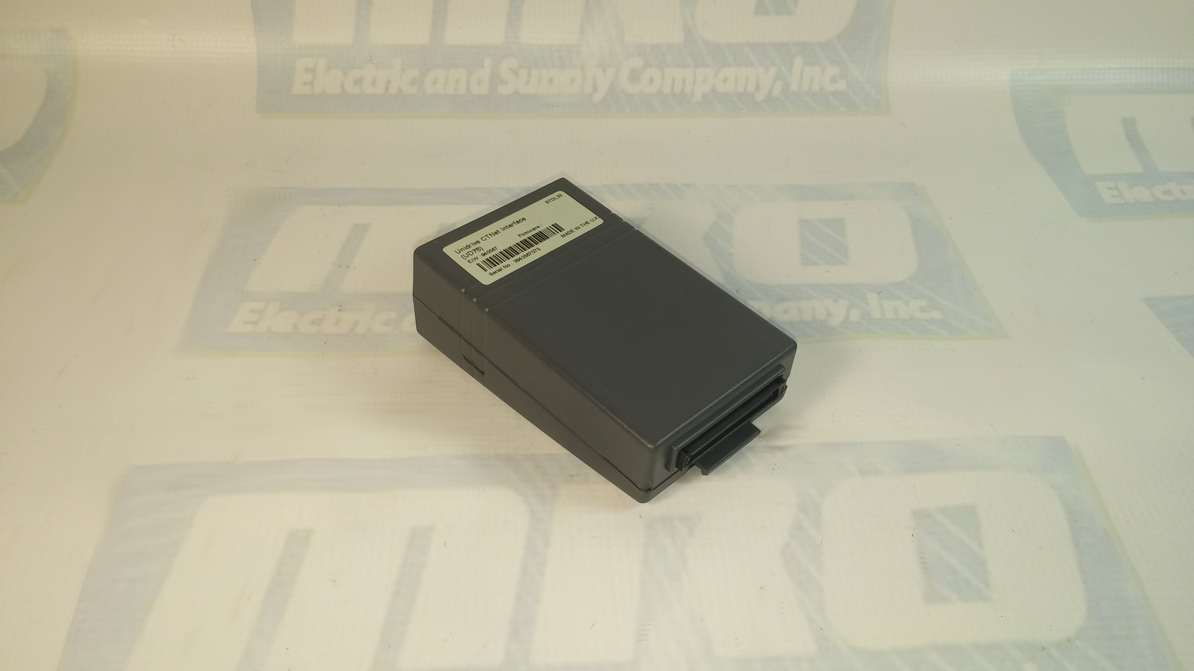
UD75 Configuration and Setup

You can check out our previous blog post  on the UD75 here for more information. Check out the UD75 product page on our website along with all of our other Unidrive options.

UD75 Configuration
  1. Isolate the drive from the mains supply and allow 5 minutes for the DC Bus capacitors to discharge.
  2. Insert Large Option Module as shown below. Ensure that it is correctly inserted. The module will click firmly into place.
  3. To remove the module, pull on the black tab, and the module will disengage from the connector and pull out of the drive.
UD75 Configuration: Cable Screen
The screen of the cable at every node on the network MUST be connected to the screen terminal (pin 3) on the CTNet terminal block. When the screen is stripped back to connect the twisted pair to the CTNet terminals, keep the exposed section of the cable as short as possible. On the CTNet PC Interface Adapter Card, there is no screen terminal. The screen should be cut and taped back to prevent it coming into contact with any other surfaces. The on-board terminal resistor should not be connected.
UD75 Configuration: Network Termination
The network MUST be fitted with terminating resistors AT BOTH ENDS!!! If resistors are not fitted, the network appear to work OK, but the noise immunity of the network will be drastically reduced. The terminating resistor value should match the nominal characteristic impedance value for the cable; in the case of the customized CTNet cable, the terminating resistors used should be nominally 78Ω. PC ISA and PCMCIA cards for interfacing a PC to CTNet are available from CT SSPD.

For price and ordering info you can email sales@mroelectric.com or call 1-800-691-8511. We have these and all the other Control Techniques Unidrive Classic option modules in stock, along with the drives themselves.

UD75 Configuration
UD75 Configuration

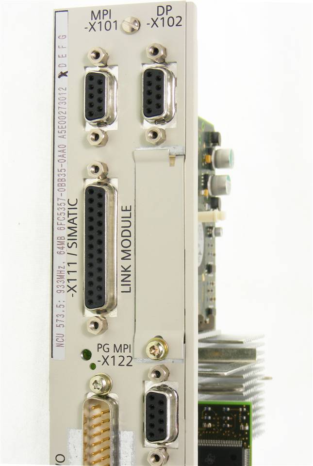
6FC5357-0BB35-0AA0 Configuration and Setup

You can check out our previous blog post on the 6FC5357-0BB35-0AA0 here for more information. Check out our websites to see all of our Siemens products.

The 6FC5357-0BB35-0AA0 configuration features a modular design comprising line filter, commutating reactor, line supply infeed module, drive modules as well as, when required: monitoring, pulsed resistor and capacitor module(s). Satisfactory operation is ensured only in conjunction with the components that are described in the 6FC5357-0BB35-0AA0 Configuration Manual or published in the Catalog NC60 (Internet Mall) and with adherence to the required boundary/application conditions. Modules can also be arranged in several tiers one above the other or next to one another.

The housings of the  6FC5357-0BB35-0AA0 converter system modules are enclosed and EMC–compatible as specified in EN 60529 (IEC 60529). The electrical system is designed to comply with EN 50178 (VDE 0160) and EN 60204, and an EC declaration of conformity is available. The connections in the module group, motor cables, encoder lines and bus lines must be made using preassembled MOTION–CONNECT lines.

Due to the limited conductivity of the DC link busbars of the modules with module width 150 mm, the DC link power PZK of these modules must not exceed 55 kW. Larger DC link busbars must be used if this restriction cannot be complied with. The DC link power PZK of the subsequent modules is calculated according to the engineering rule specified in the manual. The larger DC link busbars can be ordered as a set. The set includes reinforced DC link busbars for module widths 50 mm, 100 mm and 150 mm. The standard DC link brackets between the modules may not be changed, even when strengthened DC link busbars are used.

To order or get price you can email sales@mroelectric.com or call 1-800-691-8511.

6FC5357-0BB35-0AA0
6FC5357-0BB35-0AA0 Configuation