Joe Kaminski is an industrial automation specialist at MRO Electric. He has a background in industrial engineering and supply chain management. Joe has worked in the automation industry for over 10 years providing support to some of the largest companies in the world. For more info, visit www.mroelectric.com.
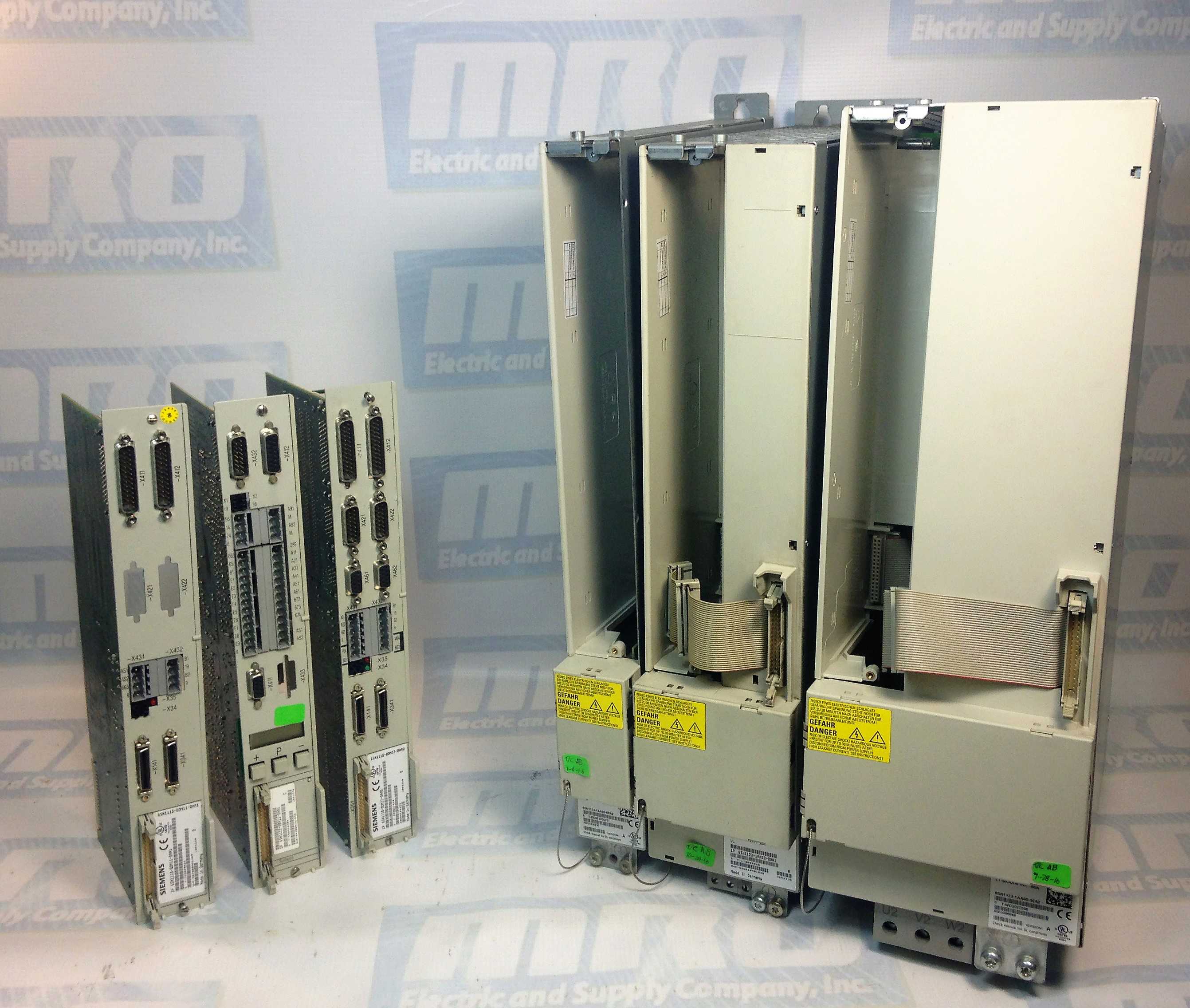
When installing a new Siemens Simodrive system, one of the first steps is to mount the drives in the cabinet. When you mount Siemens Simodrives, the modules must be arranged in a particular layout. The following criteria must be taken into account.
– Function of the module
– Cross section of the DC link busbar
The Control Techniques Commander SK series contains several levels of security. The level 1 security set has parameters from 1 – 10. These parameters are the most basic drive configuration registers, containing mostly motor information and start/stop selections. Level 2 allows you to view and modify parameters 1 – 60. These include more advanced features, such as, the brake control and fieldbus configuration. Level 3 access is used to access parameter 1 – 95. Parameters 61 – 80 in this level can be used to gain access to any register in the drive. Within level 3 you are also able to gain access to the diagnostic functions of Pr 81 – Pr 95. The last level is a custom security setting called Loc which can be used to edit any registers in the drive. Check out our website for all of our Commander SK series troubleshooting documentation.
X171: Terminal NS1–NS2 (coil circuit of the internal line supply– and pre–charging contactor):
– is used to electrically isolate from the line supply (signal contact, terminals 111–213 must be interrogated)
– may only be switched if terminal 48 is open–circuit
terminal 48: Start
– has the highest priority
– Sequence: Pre–charging ON interrogation VDClinkw310V and VDClinkw√2*Vsupply–50V
> 500ms pre–charging contactor OUT, interrogation whether OUT, main contactor IN
>1s internal enable signals (for I/R and module group)
– saved during pre–charging
terminal 63: Pulse enable
– has the highest priority for pulse enable of all the modules
– acts instantaneously (without delay)
Terminal 64: Drive enable
– acts instantaneously on all modules
– when the signal is withdrawn, nset is set to 0 for all drives, and
> for main spindle drive / induction motor module 611 A, the pulses are canceled
after a speed, which can be set, is fallen below. The drive is braked along the ramp.
> for feed drives 611 A, after the selected timer stages have expired (as supplied: 240ms) all of the controllers and pulses are inhibited. The drive brakes along the current limit.
> for 611D drives, the pulses are deleted after a selectable speed has been fallen below and/or a time which can be set, has expired. The drive brakes along the set limits. (For spindles, a ramp can be achieved via regenerative limiting [kW])
terminal 112: Setting–up operation (Vmin3–ph. 24V AC or 34 V DC)
– the VDClink
– closed–loop control is inhibited
– regenerative feedback is not possible, i.e. when braking, VDClink can be >600V!
– this function is interrogated with the start inhibit signal, terminal AS1–AS2.
terminals AS1–AS2: start inhibit signal
– terminals AS1–AS2 closed means ”start inhibit is effective” (setting–up operation) terminals 111, 113, 213: signal contact, internal line contactor
– terminals 111 – 113: NO contact
– terminals 111 – 213: NC contact
terminal 19: FR–:
– reference ground, enable voltage
– floating (connected to the general reference ground, terminal 15 via 10kΩ)
– it is not permissible to connect terminal 19 with terminal 15 (connect to PE rail or X131)
terminal 9: FR+:
– 24V enable voltage
– max. load capability of the power supply:500mA (corresponds to 8 slots;1 optocoupler input
requires 12mA)
X 141: electronic voltages:
– terminal 7: P24 +20.4 to 28.8V / 50mA
– terminal 45: P15 +15V / 10mA
– terminal 44: N15 –15V / 10mA
– terminal 10: N24 –20.4 to 28.8V / 50mA
– terminal 15: M 0V
– it is not permissible to connect terminal 15 to PE (ground loop)
– it is not permissible to connect terminal 15 with terminal 19 (short–circuit via reactor, which internally connects terminal 15 with X131)
terminal L1–L2 for 80kW and 120kW – I/R
– is used to supply the coil of the internal line contactor
– is supplied directly at the line supply with 2–ph. 400V AC (not between I/R and reactor)
– fuse: INw4 A, type gLFan connection for 80 and 120kW I/R
– 3–ph. 360 to 510V AC , 45–65 Hz directly at the line supply (not between the I/R and reactor)
– observe the rotating field (phase sequence)!
– fuse: INw1.5 A (motor protection circuit–breaker)
– conductor connection with additional connection of the power supply at the DC link
– for this operating mode, terminals 2U1, 2V1 and 2W1 of the power supply must be supplied with the line supply voltage between the series reactor and I/R, otherwise the power supply will be destroyed! This is also valid for the monitoring modules!
Ohm Checking the Simodrive Power Section
Caution! It must be assured that power is removed and the DC Bus has drained to a safe level before any connections are removed or checked!
After you are sure that the DC Bus has safely discharged , a DVM on the Diode scale can be used to detect if a short circuit or open exists in the power section. Readings will vary with module size.
Note: P600 and M600 are the 600 V DC Bus connections. U2, V2 and W2 are the motor connections.
• Disconnect the P600, M600 bus bars, U2, V2 and W2 connections. This isolates the power module from the motor and DC Bus.
• Diode check between P600 and U2, then V2 then W2. There should be continuity with the – lead on P600 and the + lead on U2, V2 or W2. Readings should be open with the leads reversed.
• Diode check between M600 and U2, V2, W2. There should be continuity with the + lead on M600 and the – lead on U2, V2 or W2. Readings should be open with the leads reversed.
• Diode check between P600 and M600. There should be continuity with the + lead on the M600 and the – lead on P600. The reading should be open with the leads reversed.
• Diode check between U2, V2 and W2. All combinations should read open.
Note: If all readings are open the internal DC Bus fuse is open. If there is a 0Ω reading, there is a short in the power circuit.
Note 2: Because of the capacitance in the power circuit, resistance checks will indicate a charging effect. It is necessary to wait until the measurement has stabilized to determine if it is correct. If possible, it is best to use a DVM with a diode check.
The Modicon Quantum PLCs provide well-balanced CPUs able to provide leading performance from boolean to floating-point instruction.
Unity Pro programming software supports five IEC languages as standard: IEC Ladder (LD), Structured Text (ST), Function Block Diagram (FBD), Sequential Function Chart (SFC), and Instructional List (IL), as well as the Modicon LL984 language to facilitate installed base upgrades.
High-level multitasking system
Memory capacity up to 7 Mb using Personal Computer Memory Card International Association(PCMCIA) extensions.
Specially designed for process control applications with conformal coated modules and an extensive catalogue of partner modules
Safety processors and I/O modules to manage Safety Instrumented Systems (SIS).
Plug & Play high-performance Hot-Standby solutions with LCD keypad for local monitoring
Adheres to open standards for communications including Ethernet Modbus® TCP/IP, EtherNet/IP (the new ODVA standard for EtherNet/IP™ incorporates Modbus TCP/IP), Profibus and others.
Numerous built-in ports (USB port, Ethernet TCP/IP port with Web server, Modbus Plus and at least one Modbus serial port) on the front panel
In-rack connectivity to Profibus® DP
Embedded Ethernet Router
Increase the availability of your architecture by using Quantum Ethernet I/O modules (QEIO) that support deterministic Remote I/O (RIO)
The Modicon X80 I/O expands your architecture and easily integrates your distributed devices in the same network (such as HMI, variable speed drives, I/O islands…)
Supports the Highway Addressable Remote Transducer (HART), the protocol for sending and receiving digital information across analog wires between smart devices and a control or monitoring system
Choose performance
Offering a large range of processors, Modicon Quantum is ideal for complex processes. The power of its processors results in optimum cycle times, while integrating even more communication functions, diagnostics, memory flexibility and data storage. The Quantum Safety system is now available, certified by TÜV Rheinland, simple to use and ready to be integrated in your automated system.
More flexibility Choose the best topology, daisy chain loop, ring, star, bus… for the design of your Ethernet architecture.
Higher availability Hot-standby CPUs and daisy chain loop topology improve the availability of your process. In the event that the cable is broken, the recovery time is less than 50 ms for an entire Quantum Ethernet I/O architecture.
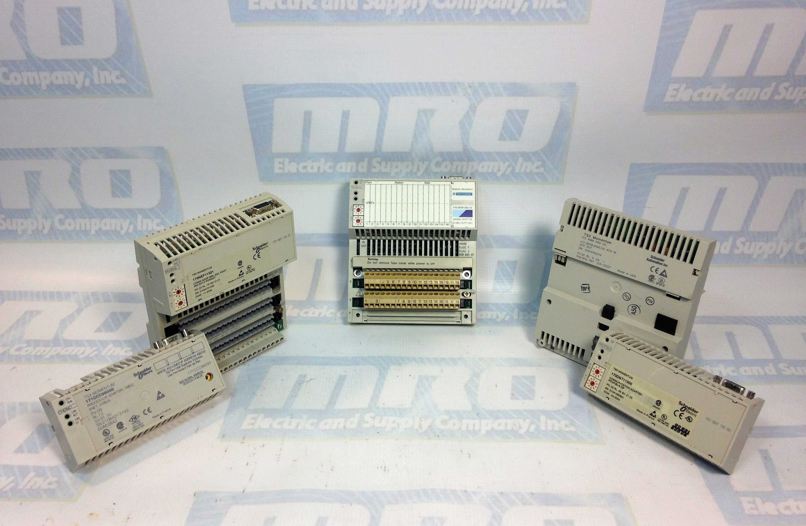
Modicon Momentum PLC
The small footprint and open architecture of the Modicon Momentum PLC product line make it extremely versatile for a variety of Unity™ Pro automation applications. Modicon Momentum PLC options and accessories include: I/O bases, processor adapters, option adapters and communication adapters that are interchangeable and snap together to deliver optimal flexibility throughout the control system life cycle.
The Modicon Momentum PLC offers:
IP 20 Monoblock I/O bases which provide the foundation for the rest of the Modicon Momentum control system and serve as the mounting base for communication adapters and processors. Over 30 I/O module types available: Analogue, Discrete, Multi-function, etc.
Processor Adapters:
Operate with a single local I/O module or in systems with up to 32 I/O modules
Built-in communication ports including, Ethernet Modbus™ TCP/IP or Modbus RS232/RS485 serial communication, USB and IO Bus
Perform functions including data acquisition, peer-to-peer communication, and I/O scanning. Embedded web pages enable the use of a standard web browser to read status and diagnostic information from the processor.
Communication Adapters snap into any of the I/O modules and include Modbus TCP/IP, Modbus™ Plus, FIPIO™, INTERBUS™, and PROFIBUS® DP.
The Modicon Momentum PLC also offers selected I/O bases, processors, and communication modules with conformal coating – ideal for applications with harsh or humid environments that require a small footprint.
Modicon Momentum Unity CPU
The Modicon Momentum Unity™ CPU allows the simple upgrade that helps you increase the capacity and efficiency of your legacy Modicon Momentum application in a cost-effective way. The Modicon Momentum Unity CPU enables you to standardize and manage your controllers on a single programming software, Unity Pro software. It delivers a low-cost and low-risk modernization path while protecting your previous investment.
Why you should modernize now.
Upgrading to the Modicon Momentum Unity CPU is the simplest modernization strategy for your legacy PLCs. Unite all your small, medium, and large controllers on the Unity Pro software platform with robust communications and state-of-the-art programming functions
Cost-effective – Preserve the existing Momentum I/O investment and import developed Modsoft™, Proworx™, or Concept™ application programs
Simple – Upgrade to a single, intuitive software suite to manage all controllers
Ready for the future – Embark on a clear path for future modernization with PlantStruxure integrated architecture