In today’s highly automated world, machines and industrial processes are controlled by sophisticated electronic devices that ensure efficiency, precision, and safety. One of the key players in this realm is the Programmable Logic Controller (PLC). PLCs are the unsung heroes behind the automation of countless industries, from manufacturing and agriculture to energy production and beyond. In this comprehensive guide, we will delve deep into the world of PLCs to understand how they work, their applications, components, programming, and their significance in modern industrial automation.
Chapter 1: The Basics of PLCs
1.1 What is a PLC?
A Programmable Logic Controller (PLC) is a specialized computer designed to control and automate industrial processes and machinery. Unlike general-purpose computers, PLCs are tailored for reliability, ruggedness, and real-time control. They are commonly used in manufacturing plants, chemical processing, power generation, and various other industries.
1.2 Why Use PLCs?
PLCs offer several advantages over traditional relay-based control systems:
Flexibility: PLCs are highly adaptable and can be reprogrammed to handle different tasks without the need for hardware changes.
Reliability: PLCs are known for their robustness, with long lifespans and resistance to environmental factors.
Real-time Control: They provide precise control over processes with minimal delay.
Diagnostics: PLCs offer extensive diagnostic capabilities, making troubleshooting and maintenance easier.
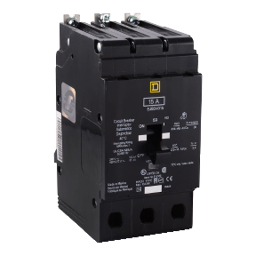
The Square D EDB34030 is a three pole, 30 Ampere circuit breaker. At 277V, this miniature breaker is reliable, sustainable, efficient and safe.
Part Number: EDB34030 Item Weight: 3.6lbs Product Dimensions: 9.7 x 6.1 x 4.5 inches Voltage: 480V Amperage: 30A Trip Rating; 875A Mounting Mode: Bolt-on Interruption Rating: 18kA
Square D EDB breakers by Schneider Electric are available in a range of amperages varying from 20A to 60A. This particular model, the EBD34030, is 30A. This breaker is set apart from other breakers because of its compact size at 9.7 x 6.1 x 4.5 inches, while the typical breaker is around 8 x 8 x 12 inches. As a bolt on mount, it is preferred in commercial and industrial applications where vibrations might be considered an issue. When installing, be sure to use the recommended #12-#6 AWG AI or #14-#6 AWG Cu Lug wire. This breaker is ideal for NF series panel-boards to offer superior overload and short circuit stability by utilizing thermal magnetic protection. It is also HACR rated, UL listed and CSA certified.
MRO Electric and Supply stocks Square D circuit breakers, including the EDB34030. For more information or to request a quote, please contact us at 800-691-8511 or at sales@mroelectric.com.
The Altistart 48(ATS48) series of soft starters by Square D and Schneider Electric allows for consistent start/stop rates that are independent of motor loads. These devices are more advanced than the standard drives that cannot control the applied motor torque. Featuring contact wiring and control, the soft starter allows for near-seamless integration with existing operations. Many preset parameters are included with the device and they cover a large spectrum of operations. Additional parameters may also be loaded up to meet specific needs. Available power ratings include:
3 – 200 HP @ 208VAC, 60 Hz
5 – 250 HP @ 230VAC, 60 Hz
10 – 500 HP @ 460VAC, 60 Hz
15 – 600 HP @ 575VAC, 60Hz
The ATS48 series features a dual configuration of two motors which allows for a cascaded start/stop in many operations. Using the Torque Control System(TCS) the unit can minimize wear on gears which allows for less time servicing the unit.
The Altistart 48 series takes advantage of the PowerSuite™ software for programming of your drive or soft starter. With this software, you will be able to monitor and document all of your operations. Configurations are easily saved via hard disk, CD-ROM, flash memory, etc. Using Ethernet technology, the user is able to configure and monitor operations on the go, and a constant feed of information allows for real-time opportunity to modify and adjust configuration files on the fly.
Troubleshooting can be an issue for people when so many different things are going on. It just isn’t feasible to stop operations every time an error occurs. Below is a list of fault codes for the ATS48 Soft Start series that will help determine most issues:
Fault Code
Description
nLP
rdY
Soft start without run command and:
• Line power not supplied
• Line power supplied
tbS
Starting time delay not elapsed
HEA
Motor preheating in progress
(Use SUP menu to set up monitoring
parameter. Factory setting: Motor Current.)
Soft start with run command
brL
Soft start braking
Stb
Waiting for a command (RUN or STOP) in
cascade mode
CFF
Invalid configuration on power-up
CFI
Invalid configuration
CLF
Loss of Control Power
EEF
Internal memory fault
EtF
External fault
ErF
Line frequency out of tolerance
InF
Internal fault
LrF
Locked rotor fault
OCF
Overcurrent fault
OHF
Soft start overheating fault
OLC
Current overload fault
OLF
Motor overload/ground fault
OtF
Motor thermal fault detected by PTC probes
PHF
Loss of line or motor phase
PIF
Phase reversal fault
SLF
Serial link fault
StF
Excessive starting time
ULF
Motor underload fault
USF
Lack of AC line power on a run command
MRO Electric and Supply carries all models of this unit and has a fast and easy repair service to get your unit fixed and back into your hands as soon as possible.
Struggling with your ATS48 Soft Starter?
MRO Electric provides the insights and assistance you need to troubleshoot efficiently. Our inventory is stocked with the necessary parts, and our experts are on standby to help you minimize downtime.
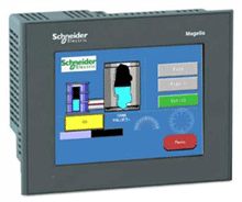
Any amount of downtime is too much for most companies. Parts will break from time to time, and repairs will be necessary. Here at MRO Electric and Supply we are dedicated to providing the best service making sure that your downtime is minimal. Human Interface Terminals(HMIs) are a crucial part of any automation process nowadays, so it is important to make sure it is working correctly. Along with selling both new and remanufactured products, MRO Electric and Supply offers both repair and exchange services.
Modicon was the first manufacturer to release programmable logic controllers onto the market, and since have been one of the top brands for PLC’s. MRO Electric and Supply have all the parts necessary to run the Magelis HMI at it full potential, including panels, cables, controllers, adapters and any software that may be needed. Along with repairs, we handle installations and programming of drives and controllers so that you don’t have to.
We also offer the option to retrofit your old machines with newer interfaces for the most up-to-date applications and processes. By fitting existing HMI’s with new interfaces you are able to add years to the life span of your automation set up. It is a lot easier to update and fix your existing displays and HMIs than taking the time and money to purchase and fit new parts.
All of our repairs come with a 12 month guarantee. Our repair service is based on doing the right job, and getting your part back to you as soon as possible. Every part we refurbish is tested to make sure they work the way they are supposed to. Our factory-trained technicians have many years working with Modicon products.
For a free Modicon Magelis HMI repair quote, please email sales@mroelectric.com or call 800-691-8511. For more information on our Modicon repair capabilities, you can visit our Modicon Repair page.
The Schneider Electric TSXCUSBMBP is a USB Modbus Plus Communications Adapter. In this guide, we will show you how to install the hardware, configure the driver software, and use the Modbus Plus network diagnostics features of the driver software.
Important: The least versions of the TSXCUSBMBP driver to run on Win Server 2012 R2 are driver versions 8.0 and 8.1.
The TSXCUSBMBP is designed to bridge the gap between a USB connection and the Modbus Plus network. It combines hardware and software together in one simple and single device. The module has its own Modbus Plus node address which can be set through the TSXCUSBMBP driver software. This module allows software applications using the serial Modbus RTU communications to connect on the high-speed Modbus Plus network, as well as provide diagnostic capabilities to the Modbus Plus network.
Most Win32 Applications that support serial Mdubus communications can use a Modicon TSXCUSBMBP to connect on a Modbus Plus network. A VSP (Virtual Serial Port) is what redirects communications from Concept, Unity, ProWorx32 and other programs to the TSXCUSBMBP communications adapter. After the VSP is installed, it will create one serial port with the port reference as defined in the module’s driver software. When configuring the Modbus application software, this port reference is selected as the serial port for the application to use. The routing table is used to associate Modbus Slave IDs with 5-byte Modbus Plus routing paths which allow the application software to communicate with any Modbus Plus device within range on the network.
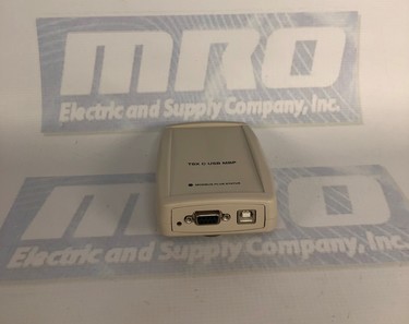
The TSXCUSBMBP’s hardware consists of a box with a USB cable from one end (which connects to the PC) and a standard Modbus Plus DB9 connector on the other end (for the Modbus Plus network). Local signalling LEDs on the top cover of the device tell you the presence of power from the USB port and the state of the Modbus Plus network – no external power supply is required.
TSXCUSBMBP Installation
To install the TSXCUSBMBP, you will need the following: – Windows XP Operating System with service pack 2, or Windows 2000 with Service Pack 4 or greater. – 1 MB of free disk space. – Minimum of 256 MB of RAM. – One free USB port or a USB Hub that supports USB 1.1 or greater.
If a previous version of the TSXCUSBMBP was installed, the VSP component of the driver must be manually uninstalled using Device Manager before a new version can be installed. After this, the new driver should be installed before connecting the new TSXCUSBMBP to the PC. After the new driver is installed, connect the TSXCUSBMBP and install using the New Hardware Wizard. After completing the instructions, you should see a message stating “Your new hardware is ready to use.” Restart your computer, and the device should be fully functional. If the driver starts up before the TSXCUSBMBP is connected, then it will be necessary to re-scan for adapters so the driver can detect it.
TSXCUSBMBP Configuration
To configure the module, you will need to do the following:
1. Configure the Modbus Plus Node Address The communications adapter must be assigned a Modbus Plus node address to communicate on the network. Select “Settings” and then type the address in the appropriate box. When complete, hit “Save”.
2. Configure the Slave Response Timeout The slave response timeout is used by the module each time it sends a request from an application out on the network to a slave device. Use the manual to determine the appropriate value that should be used with your system. Select “Settings” and then type the value in the appropriate box. When complete, hit “Save”.
3. Configure the Virtual Serial (COM) Port To do this, select “Virtual Modbus Port.” Select the desired COM port from the list available. When complete, click “Save”.
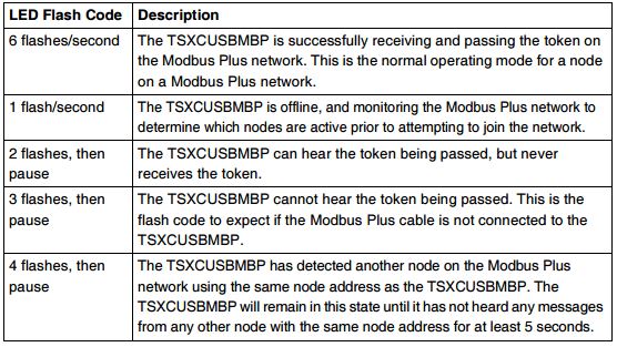
If you experience any problems while configuring your adapter, please use the table below to determine the appropriate error code given by the LEDs, if applicable. As always, refer to the user manual for more complete information.