A Complete Guide to Relays: What They Are & How They Work

Relays, are an often overlooked, but pivotal component in modern technology, serving as the silent orchestrators behind a wide range of electronic operations. Whether controlling high-power machinery or everyday devices, relays play a crucial role in transferring signals and power without direct electrical connections. Relays are used across a wide range of devices and applications, from industrial automation to consumer electronics, and understanding how they work, is key to fully utilizing their capabilities.

What Is a Relay?

A relay is an electrically controlled switch that has the ability to turn a circuit on or off. Depending on the application relays can do a number of things. Relays can be used as electrical switches to turn things on and off, or as amplifiers to convert smaller currents into larger ones. They can also be used to control a circuit with a low power signal or when multiple circuits need to be controlled by a single signal.

There are two kinds of relays, electromechanical and solid state. In this post, we will be focusing on electromechanical relays and how they work.

Why Are Relays Important?

Electrical relays are crucial because they enable the control of high-current loads using a small amount of electrical current. Relays apply voltage to the coil, which causes a low current to flow through it. This allows a larger current to pass through the contacts and control the electrical load. Relays are essential for applications where low-power control signals need to command high-power circuits.

What Are the Parts of a Relay?

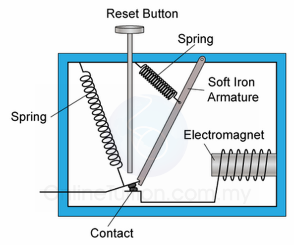
Armature– is a basic metal piece that is balanced on a pivot or a stand. It is considered the moving ‘arm’ of the relay. It makes or breaks the connection with the contacts connected to it.

Spring– is connected to one end of the armature and pushes the armature back into place if no current is passing through.

Electromagnet– is a metal wire wrapped around a metal core. The wire does not have magnetic property but can be converted into a magnet with the help of an electrical signal.

Yoke– is a small metal piece affixedon a core which attracts and holds the armature when the coil is energized.

Contacts– conductive material that exists within the device whose physical contact opens or closes a circuit

A break refers to the number of locations on a circuit that a switch can make or break the flow of current. In electromechanical relays, there can be single breaks and double breaks. A single break is usually used with low power devices while a double break is usually used with high power devices.

A pole refers to the number of circuits that relays can pass through a switch. A single pole contact carries current through one circuit, while a double can carry it through two.

A throw refers to the number of separate wiring paths. For example, a triple throw switch can be connected to one of three contacts instead of one.

How Do Relays Work?

A gray relay with the relay parts labeled
Source:
https://www.electronics-tutorials.ws/io/io_5.html

In an electromechanical relay, a small circuit has the ability to switch a larger circuit on or off through contacts by using an electromagnet. Some contacts come in different configurations depending on the use of the relay, namely, normally open relays and normally closed relays.

With a normally open (NO) relay, contacts are open when there is no current passing through. Once power is presented, the electromagnet will be activated. When charged, the electromagnet creates a magnetic field that attracts the armature and closes the contacts.

With a normally closed (NC) relay, contacts are closed when there is no current passing through. Unlike normally open relays, when normally closed relays become activated, the circuit will open and cause the current to stop flowing.

The flow of electrical current through a coil that causes the relay’s armature to move and close contact, completing the circuit

What Are the Different Types of Relays?

Electromechanical relays can be broken down into the following distinct categories: general purpose relays, machine control relays and reed relays.

General Purpose Relays

General purpose relays are electromechanical switches that typically function via a  magnetic coil. Using an AC or DC current, general purpose relays often run at voltages such as 12V, 24V, 48V, 120V and 230V. Additionally, they can command currents ranging from 2A-30A. These relays are sought after due to them having a multitude of switch configurations and being cost-effective.

Machine Control Relays

Like general purpose relays, machine control relays are operated by a magnetic coil. Typically used to control starters and other industrial elements, these relays are robust. While this gives them greater durability, it also means that they are less economical than general purpose relays. However, with additional accessories and functionality, they have an advantage over general purpose relays.

Reed Relays

Reed relays consist of two reeds, which can open or close when controlled by an electromagnet. These small relays can operate up to eight reed switches, which are typically found inside of the electromagnetic coil. When the magnetic force is removed, the reeds return to their initial open position. Since the reeds are only a short distance apart from each other, reed relays work rather quickly. There are many benefits of using a reed relay, as their hermetic seal prevents the passage of contaminants. Additionally, this seal enables reed relays to have dependable switching.

There are many things to consider when choosing a relay for a project. Lifespan, operating environment, mechanical loads, size, and number and type of contacts are all important factors in choosing the right relay.

What Are the Pros and Cons of Using Relays?

While electromechanical relays have a variety of uses, different applications require different automation devices, and electromechanical relays may not always be the best fit. To help you determine if an electromechanical relay will work for you, we have highlighted some of the advantages and disadvantages below.

Advantages

  • Fast operation and reset
  • More definitive ON/OFF
  • Simple and most reliable

Disadvantages

  • Suffers the effects of age
  • No directional features
  • Needs a large amount of input power to operate

What Is a Relay Used For? Relay Applications

Relays protect electrical systems by preventing and reducing the damage to the connected equipment from over currents and voltages. Relays protect a wide range of equipment by detecting and isolating faults in a power transmission and distribution system.

Since electrical relays can control a high-voltage circuit using a low-voltage signal, they can help prevent damage to valuable electronics and components, including modems, amplifiers, and even the starter in your car.

Other applications for relays include:

  • Automotive
  • Appliances
  • Lighting systems
  • Telecommunication components
  • Industrial controllers
  • Electrical power protection systems
  • Traffic control

How Do You Test a Relay?

While relays are generally dependable, they can still experience faults like any other component. Thankfully, testing a relay is a relatively straightforward process– all you need is a multimeter. Read on to learn how to identify a faulty relay step-by-step.

  1. Locate the relay: Find where the circuits enter and exit the relay. This region is typically marked by pins or terminals.
  2. Check for voltage: With the multimeter set to measure voltage, probe the point where the relay plugs into the circuit. If it does not detect any voltage, inspect the associated fuse or switch for any defects that might interrupt the power supply.
  3. Test ground connection: If voltage is present at the connection point, switch the multimeter to the continuity or resistance function and check for a good ground connection on the opposite side of the relay. A faulty ground can cause the relay to malfunction.
  4. Verify power source: After successfully checking for voltage and testing the ground connection, check the voltage where the relay connects to the battery or another power source. If the multimeter detects no voltage here, it suggests a potential issue with a fuse or circuit breaker.
  5. Test component connection: Use the multimeter’s continuity function to ensure a strong connection between the relay and the component it controls. If continuity exists and the previous steps did not reveal any other faults, it is likely a defective relay.

How Do You Identify a Faulty Relay?

Although relays are considered reliable mechanisms, they do have the capability of failing. Determining whether you have a faulty relay is simple and can be easily identified with the help of a multimeter. 

Here are a few tips on how to use your multimeter to test a relay:

  1. Remove the relay from the fuse box or vehicle.
  2. Determine where the input and output points of the circuit are located on the relay.
  3. Make sure your multimeter is set to ohm.
  4. Connect the leads of the multimeter across the entrance and exit pins to determine resistance. Ideally, you’ll see a reading between 50 to 120 ohm.
  5. If your multimeter has a reading of Open or Out of Range you may have a defective coil winding and the relay will need to be replaced.
  6. If the reading looks good, you’ll want to connect the leads in between the switch pins. You should see a reading of OL or Open.

MRO Electric and Supply has an extensive inventory of relays in stock.  Please email sales@mroelectric or call us at 800-691-8511 for a quote.

Control Techniques Manufacturer Showcase

Established in 1972 in Newtown, Wales, this industrial part manufacturer owned by the Nidec Corporation continues to provide high quality AC Drives and motor control management products today. In this post, we will be showcasing some of the classes and parts Control Techniques has to offer.

Unidrive
The Unidrive line of products from Control Techniques includes devices like brushless AC servo motors. The Unidrive Classic series drives are available in five different sizes and twenty-six different models, allowing you to fit one of these devices in almost any existing automation system. This series of drives have enough built in parameters to meet most task demands.

UNI2403 by Control Techniques

The Unidrive Classic series offers complete I/O configurability, advanced position control, programmable logic functions, regeneration mode for four-quadrant operations, high speed communications for quick feedback, preset macros for simplified operations and more.

Focus DC
The Focus DC line of products are solid state analog DC drives built to last reliably in almost all environments. This family has regenerative models and different enclosure kits available to offer a wide range of custom configurations. Optional kits for these drives include ones that offer toggle switches, signal isolation, M contactor kits, dynamic braking and tachometer feedback modules.

Commander SE
The Commander SE line of products offer flexibility in many automated systems by being the top choice for microdrives. They are built to be rugged machines that can stay physically stable and constantly sit at correct temperatures. These devices are shipped with shipped with firmware that makes first time setup and installation as easy as possible, including the parameters that immediately meet the needs of most drive applications.

Commander SE products by Control Techniques

The Commander SE series offers full control of all levels of parameters, visualization of terminal connections, multiple motor speed preset settings, open loop vector control, fully configurable analog/digital Input/Output settings, sequenced switching between multiple parameters and communications via DeviceNet, PROFIBUS DP and Interbus S.

Unidrive SP
The Unidrive SP series comes in both free-standing and modular forms. The SP modular offers all the benefits of the normal Unidrive SP system along with more intense system power configurations. It is easily able to be connected together to create almost any custom setup necessary. Parallel drives are used together for higher powered motors. These drives are built to last and are flexible.

Some additional modules include SPMA AC in / DC out Drive, SPMC AC in / DC out Rectifier, SPMD DC in / AC out Inverter, SM Control MASTER, SM Control SLAVE, SPM Power Selector.

MRO Electric and Supply offers a variety of new and refurbished Control Techniques devices. We also offer repair pricing. For more information, please call 800-691-8511 or email sales@mroelectric.com.

Product Spotlight: Square D EDB34030 Circuit Breaker

The Square D EDB34030 is a three pole, 30 Ampere circuit breaker. At 277V, this miniature breaker is reliable, sustainable, efficient and safe.

Part Number: EDB34030
Item Weight: 3.6lbs
Product Dimensions: 9.7 x 6.1 x 4.5 inches
Voltage: 480V
Amperage: 30A
Trip Rating; 875A
Mounting Mode: Bolt-on
Interruption Rating: 18kA

Square D EDB breakers by Schneider Electric are available in a range of amperages varying from 20A to 60A. This particular model, the EBD34030, is 30A.
This breaker is set apart from other breakers because of its compact size at 9.7 x 6.1 x 4.5 inches, while the typical breaker is around 8 x 8 x 12 inches. As a bolt on mount, it is preferred in commercial and industrial applications where vibrations might be considered an issue. When installing, be sure to use the recommended #12-#6 AWG AI or #14-#6 AWG Cu Lug wire. This breaker is ideal for NF series panel-boards to offer superior overload and short circuit stability by utilizing thermal magnetic protection. It is also HACR rated, UL listed and CSA certified.

MRO Electric and Supply stocks Square D circuit breakers, including the EDB34030. For more information or to request a quote, please contact us at 800-691-8511 or at sales@mroelectric.com.

What are circuit breakers?

A circuit breaker is a preventative safety device that detects and stops a circuit if the current is insufficient or in excess. These devices help insure the stability of the electric current in our buildings. Unlike fuses, breakers are reusable and can be consistently relied upon to break a circuit to protect us from potential electrical fires.

How do they work?

A breaker is comprised of a few basic components. A switch is connected to an electromagnet that allows electricity to flow from the bottom to the top terminals.

Source:
http://spmphysics.onlinetuition.com.my/2008/06/uses-of-electromagnet-circuit-breaker.html

With current running through the electromagnet, it becomes magnetized. If the current is suddenly increased, the magnet becomes strong enough to pull down a metal lever attached to the switch linkage. By doing so, the contacts are broken and the electricity is powered off.

What’s the difference between certain breakers?

Residential Circuit breakers- Used in common household wiring to protect electrical appliances like refrigerators, washing machines and fans. Electrical panels can also be designed to have one breaker controlling one specific or multiple outlets in a room that shut off when overloaded.

Industrial Circuit breakers- Used with much larger electrical current applications for warehouses, factories, and other large industrial locations. They can be used to insure safety of the plant equipment, lighting, business systems, air conditioning and wiring.

Voltage– Describes the ‘pressure’ of the electricity. The most common voltages of breakers are . Most household voltage is 120V, with larger appliances around 240V.
Amperage– Measures strength of the current in amperes. Common amperages include 15A, 20A, 25A, up to 6000A.
Pole number– Describes the number of completely separate circuits that can be protected by a circuit breaker at the same time. These include single-pole, double-pole, triple-pole and tandem pole breakers.
Installation location/External Design– Breakers can be designed to be indoor or outdoor based on the application. Different enclosures can be made to withstand different weather conditions.
Interrupting Mechanism– Other breaker designs include air circuit, oil circuit, vacuum circuit, MCB, MCCB, GFI, GFCI and AFCI breakers. While these all serve the same purpose of breaking electrical current in the event of unstable electric power consumption, they have different means of interrupting the current.


Visit MRO Electric and Supply’s website to see all of our available Circuit Breakers. If we don’t have what you need listed on the site, contact us at sales@mroelectric.com or (800)691-8511 and we will be happy to help.

Considerations for buying automated parts

What are automated parts used for?

Automation is crucial in manufacturing and is the backbone of our industries. Robots can automate highly variant, dangerous and exhausting tasks in a high-quality and cost effective way. By increasing productivity at a lower cost, maximum cost efficiency is reached, which is ideal in a business setting.

What should I be looking for when buying automated parts?

There are a number of things to keep in mind when buying automated parts for your warehouse or setup. Below is a basic guide with questions to ask yourself to make the process a little easier.

Is there a warranty? If so, for how long?

Protect your investment on your automated parts. Warranties are important in insuring that your part is functioning as intended and in getting what you paid for. Make sure you check under what instances a warranty can be claimed and how long the warranty lasts. Are there detachable parts within the automated component that are covered? MRO Electric and Supply offers a minimum 12-month warranty on all listed parts.

Is the part compatible with the machinery that is already there?

There are a multitude of environments that certain parts can be more oriented towards, including in aerospace and automotive manufacturing, food processing plants or laboratories. It is essential that the part be used in the correct application to be effective. It is obviously important that the automated component works with the setup already in place. Some additional compatibility questions to ask yourself before buying:

Does the weight or form factor impact its compatibility? Is space an issue?

Many people are eager to buy large parts for their warehouses without considering the space to put them. Consider the part and its intended configuration. Include additional equipment that comes along with the part like peripherals, fencing, light curtains or mat guards.

Will the condition of the part affect its lifespan in this application? Is there a newer, better part for this application?

Check to see if the part is new, used or refurbished, and if the condition will affect its application. Many industrial parts are discontinued as new technologies evolve, and while these legacy parts are still useful, newer components might work more efficiently or effectively. Check to see if there are any advantages or disadvantages to older and newer generations of your part and weigh your options.

Visit MRO Electric and Supply’s website to see our selection of automated parts from manufacturers like Yaskawa, Modicon, Control Techniques, Siemens, and FANUC. If we don’t have what you need listed on the site, contact us at sales@mroelectric.com or (800)691-8511 and we will be happy to help.

Yaskawa Drive Types

Yaskawa

Yaskawa Electric is a global manufacturer of high-quality parts used in robotics and automation. They specialize in servos, controllers, switches, robots, drives and more. These parts are used for a variety of purposes in industry. In this post, we will be distinguishing the different types of Yaskawa drives.

CIMR Drives
E7 Drives– Designed for commercial HVAC applications. Embedded with Modbus, APOGEE FLN and Metasys N2.
F7 Drives– Well-rounded drive with a variety of uses. Contains NEMA Type 12 enclosure with space to expand filters, fuses, I/O cards and more.
G7 Drives– Low voltage drive that uses 3 level control to combat problems with long motor cables and premature motor bearing failure. Great vector performance and flexibility. Configured options with pre-engineered cabinet options available.
P7 Drives– Created for applications with variable torque like centrifugal pumps and fans.

yaskawa p7

GPD Drives
GPD 333– General purpose AC Drive, 1/4 the size of normal PWM drives.
GPD 503/505/506– High-performance three phase voltage/frequency output with adjustable speed control.
GPD 515– PWM AC drive designed for low motor noise and high starting torque.

Microdrives
J1000 Drives– General purpose drives with open loop voltage/frequency control with preferred parameter feature. Simple variable speed of up to 7.5HP.
V1000 Drives– Compact current vector drive designed for efficiency and maintainability. Capable of up to 25HP. Economical for basic variable speed applications.
V1000-4X Drive- The same as the V1000 but with an enclosure built for dust tight environments.

Other Drives
A1000 Drives – High performance general purpose drive capable of up to 1000HP. Used for general purposes.
P1000 Drives – Torque performance capable of withstanding 1000HP. Oriented towards variable torque applications including centrifugal pumps and fans. Configured and bypass options available.
U1000 Industrial Matrix Drives – Regenerative high performance vector drive capable of up to 800HP. Used for general purposes.

Source: https://www.yaskawa.com/

Visit MRO Electric and Supply’s website to see all of our available Yaskawa Drives. If we don’t have what you need listed on the site, contact us at sales@mroelectric.com or (800) 691-8511 and we will be happy to help!