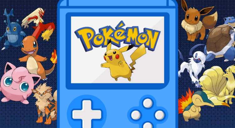
From trading cards to Nintendo Switch battles, Pokémon has been a staple in pop culture for nearly three decades. But which pocket monster captures the most hearts across the U.S.? We analyzed Google Trends search data over the past 20+ years to uncover the most searched Pokémon in every state. Whether you’re team Pikachu or partial to a more mysterious pick, this map of America’s favorite Pokémon reveals where fan loyalties lie.
The Most Popular Pokémon in Every State
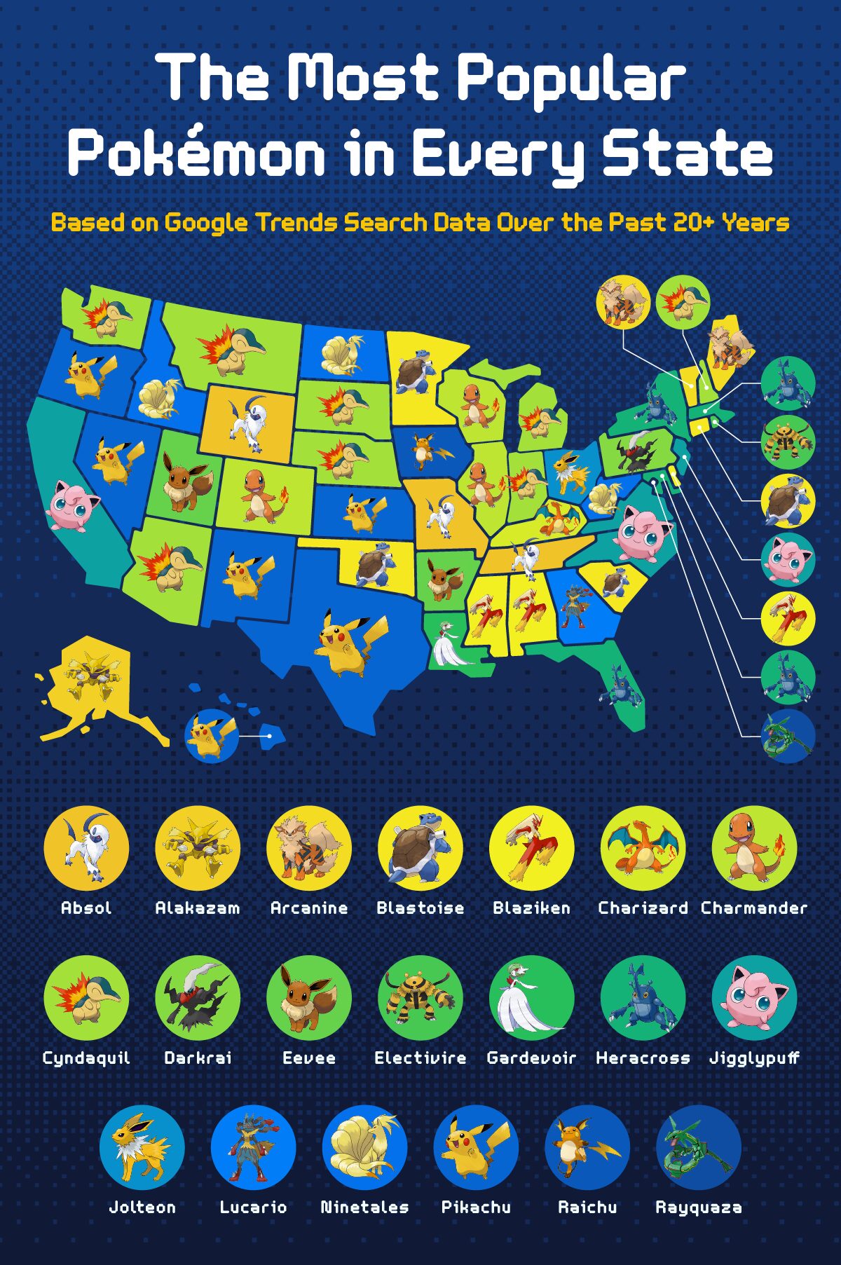
From electrifying classics to underrated evolutions, each U.S. state has its own Pokémon preference—and the trends are more surprising than you’d think. By analyzing Google Trends search interest, Cyndaquil emerged as a national favorite, capturing the top spot in eight states, including Arizona, Indiana, Michigan, and Washington. Its consistent appearance in both the Midwest and the Mountain West points to a regional fondness for this fiery Johto starter.
Pikachu, arguably the franchise’s most iconic figure, claimed dominance in six states, such as Hawaii, Texas, and Oregon, proving its enduring appeal from coast to coast. Notably, states like Nevada and New Mexico also showed strong interest in the beloved electric mouse, reinforcing Pikachu’s universal charm.
Other nostalgic favorites, such as Blastoise and Jigglypuff, also had strong showings. Blastoise was the top searched in Connecticut, Minnesota, Oklahoma, and South Carolina, while Jigglypuff’s melodic mischief resonated in California, New Jersey, North Carolina, and Virginia. Meanwhile, Ninetales—known for its mystical aura—stood out as the favorite in Idaho, North Dakota, and West Virginia, highlighting a possible coastal-to-heartland appreciation for more elegant, fox-like Pokémon.
Unique picks also dotted the map: Washington D.C. went with the legendary Rayquaza, Ohio preferred Jolteon, and Rhode Island singled out Electivire. Even lesser-hyped names like Absol and Arcanine saw multiple state wins, with Absol topping the lists in Missouri, Tennessee, and Wyoming, and Arcanine being favored in Maine and Vermont.
Which Pokémon Shines Above The Rest?
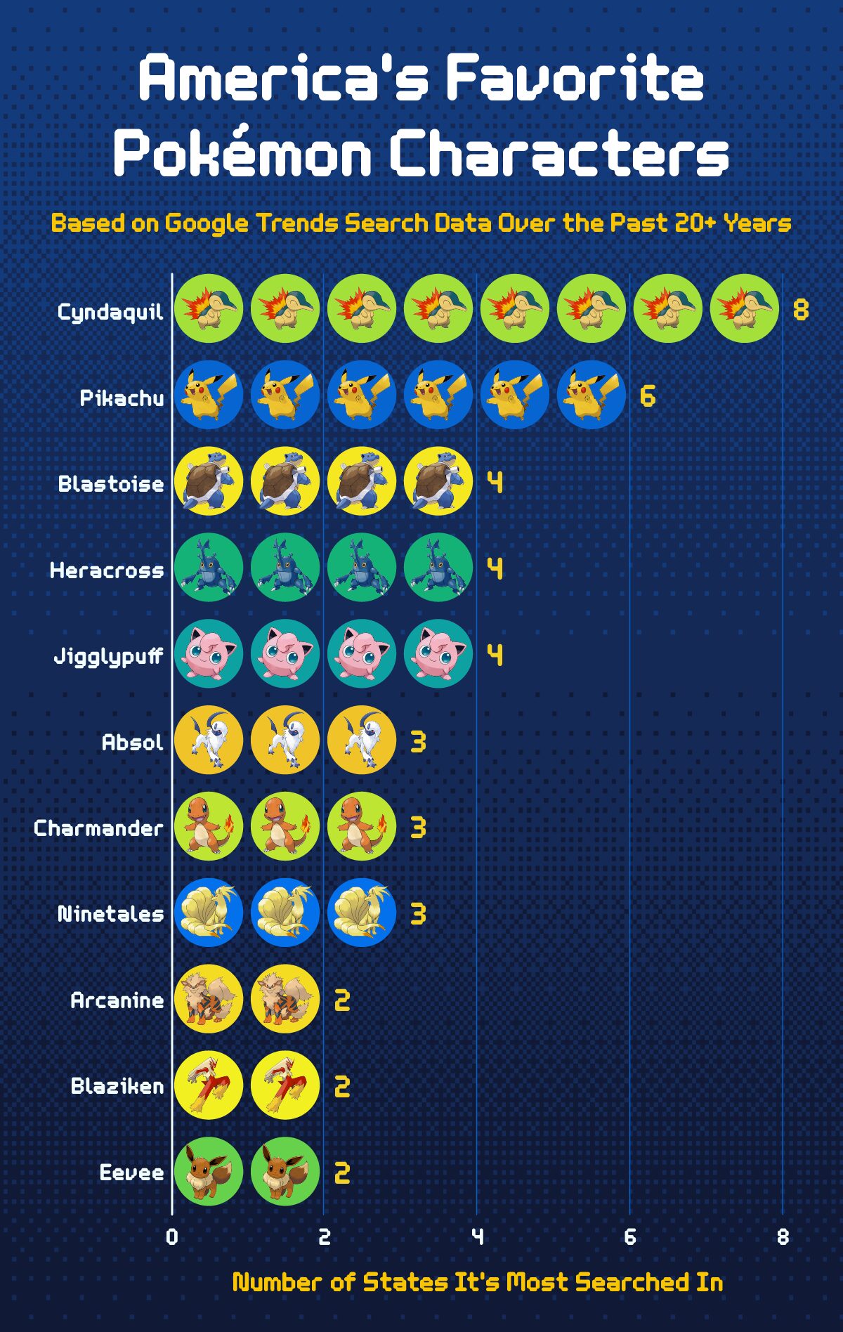
Zooming out from the state-by-state breakdown reveals a clear top-tier favorite: Cyndaquil. This Fire-type starter from the Johto region claimed the number one spot in eight states, far outpacing other Pokémon in our search analysis. Its widespread appeal may stem from a combination of nostalgia—many Millennials and Gen Z players first encountered Cyndaquil in the Pokémon Gold and Silver era—and a fondness for its unassuming design that evolves into the formidable Typhlosion. It’s official, Cyndaquil, America chooses you!
Close behind is Pikachu, leading in six states and proving that being the mascot of a multi-billion-dollar franchise still carries weight. Pikachu’s presence across various forms of media—from video games and anime to merchandise and movies—makes it one of the most recognizable and beloved characters in the world, and its popularity across both primarily urban and primarily rural states suggests universal appeal.
Blastoise, Heracross, and Jigglypuff each dominated in four states. Blastoise, a powerhouse final evolution, likely resonates with fans who value strength and reliability. Heracross, on the other hand, might surprise some, but its appearance in several Johto episodes and its unique Bug-Fighting type combination could explain its niche yet consistent fan base. Meanwhile, Jigglypuff’s cutesy appeal and long-standing role in the Super Smash Bros. series likely contribute to its steady popularity.
Pokémon like Absol, Charmander, and Ninetales each took three states. Absol’s enigmatic design and association with disaster may intrigue fans looking for something darker. Charmander, another starter Pokémon, holds a special place in the hearts of longtime fans. And Ninetales, with its elegant design and lore-inspired background, appeals to those who enjoy the mystical and majestic side of the Pokémon universe.
While many expected heavyweights like Charizard and Lucario to rank higher, they only topped the charts in one state each, possibly due to their saturated presence in franchise marketing, making them feel less novel to today’s fans.
Which Pokémon Generation Is Favored by the Most States?
- Generation I: 11 Pokémon
- Generation III: 4 Pokémon
- Generation IV: 3 Pokémon
- Generation II: 2 Pokémon
When it comes to Pokémon popularity, the classics still reign supreme. Generation I—the original 151—dominates the list with 11 of the most searched Pokémon across U.S. states. From household names like Pikachu, Charizard, and Blastoise to fan-favorites like Arcanine and Jigglypuff, these Pokémon continue to resonate with fans decades after their debut. This trend likely reflects the lasting impact of the franchise’s early success and the nostalgia associated with its first wave of games and anime episodes.
Meanwhile, Generation III and IV Pokémon hold their own, contributing four and three top-ranked Pokémon, respectively. Pokémon like Blaziken, Gardevoir, Rayquaza, and Lucario gained traction through their roles in key game titles and continued prominence in competitive battling. Their presence on the list signals a strong showing from the early 2000s generation of players who grew up during the Game Boy Advance and Nintendo DS eras.
Generation II, surprisingly, is represented by only two Pokémon—Cyndaquil and Heracross—despite being home to many beloved characters. While Cyndaquil’s wide appeal helped it become the most favored Pokémon in the nation, the overall underrepresentation of Generation II may suggest that, although it’s loved, it hasn’t maintained the same broad cultural imprint as Generations I and III.
Closing Thoughts
Whether it’s Cyndaquil’s underdog charm, Pikachu’s evergreen popularity, or the unexpected rise of Heracross, each state has its own favorite—and its reasons for that loyalty.
Just like Pokémon fans have their go-to favorites, manufacturers and engineers rely on trusted solutions to keep their operations running smoothly. At MRO Electric, we specialize in repairing and supplying top-tier industrial automation components, including those from brands such as Schneider Electric, Control Techniques, Modicon, and others. Whether you’re tackling unexpected downtime or planning for long-term system upgrades, contact us today to ensure your operations stay strong, reliable, and battle-ready.
Methodology
To determine the most popular Pokémon in every U.S. state, we compiled a list of fan-favorite characters sourced from Guidestrats, Game Informer, and Comic Vine. We then analyzed Google Trends data from 2004 to the present, measuring search interest for each Pokémon across all 50 states and the District of Columbia. The Pokémon with the highest relative search interest in each state was identified as that state’s favorite. High search volume was used as an indicator of popularity, reflecting public curiosity and fan engagement at the state level.