Diagnosing your FANUC Current Alarm

If you are getting a high current alarm on your FANUC motor, it is going to be caused by either the motor itself, the drive, or a cable. To begin the process of figuring out which alarm you are receiving you must disconnect the leads from the motor. Try powering it up and look to see if the alarm LED is lit. Fanuc alarms include the HC LED, alarm 8/9/A/B for Servo motors, and alarm 12 for Spindle motors.
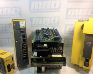
  • If you no longer are seeing an alarm, the motor is most likely bad.
  • If you have powered the motor and are receiving the alarm, the issue is most likely with the drive.

Because you have disconnected the leads from the motor, you are able to use an ohm meter/megger to monitor the power levels of the cable and motor, and make sure they are working as intended. Using a megger will help you decide if your motor is grounded correctly where an ohm reader will let you know if your motor has shorted.

Using your ohm meter check for shorts both leg-to-leg and leg-to-ground on each of the legs. The leg-to-leg readings should be consistently low between every leg while the leg-to-ground readings will stay open. The megger is used to check between the leg and ground to see if the problem could be with the terminal box on the motor or any cables connected to it.

Sometimes you may not have the necessary equipment to make a diagnosis on your motor or to troubleshoot, but we do. MRO Electric and Supply offers high quality repair services on all motors so you don’t have to worry about it. Check out our website to see all available brands and parts we can service for you.

MRO Electric and Supply has new and refurbished FANUC CNC parts available. We also offer repair pricing. For more information, please call 800-691-8511 or email sales@mroelectric.com.
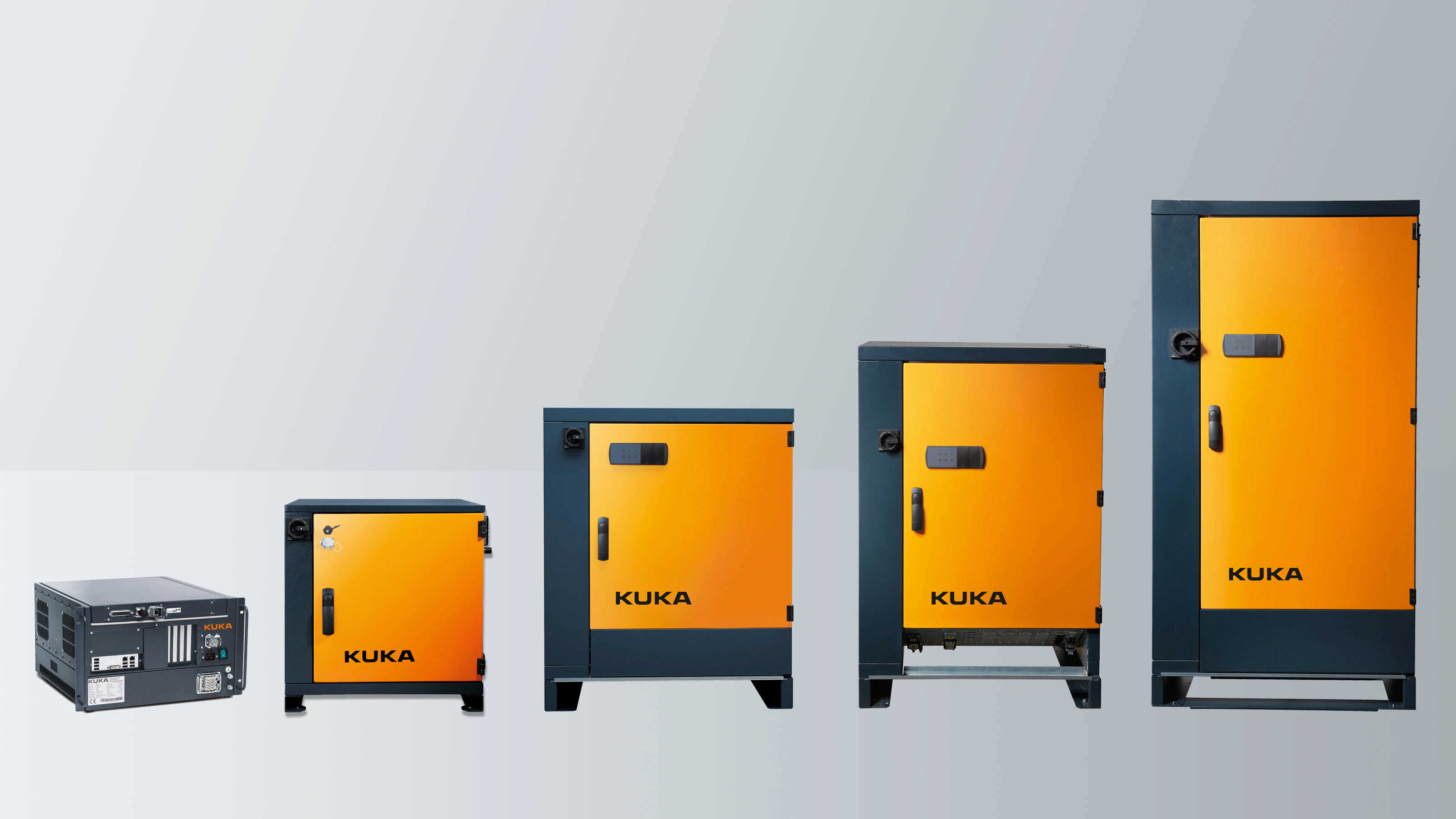
KUKA Controllers lineup

KUKA Error Codes

 KUKA robotics offers a broad range of robotics controllers and other robotics parts for a variety of industries including CNC machining, surface processing, loading usage, and much more. One common challenge with operating robotics controllers is understanding what the error codes mean, that they display when they encounter an issue. Listed below are common KUKA error messages that you may encounter while troubleshooting issues with KUKA controllers. These codes are applicable to all KUKA controllers, including the KRC1, KRC2, KRC3, and the KRC4.

Common KUKA KRC1, KRC2, KRC3, and KRC4 Error Codes

Error Code 14 – SOFTPLC: @P1@

Error Code 284 – Accu–voltage at <kps number> below <voltage level> during last buffering

  • Cause
    • The accu voltage was too low at the last switch off to buffer the
      shutdown.
    • The accu is not charged correctly anymore.
    • The accu is too old or broken.
  • Effect
    • Eventually loss of reference.
    • Cold boot.
    • Active commands inhibited
  • Remedy
    • Exchange accu.

Error Code 310 – Safety Circuit for drives not ready

  • Cause
    • Safety circuit is telling drives not to move.
    • Faulty X11
    • Faulty ESC board
    • Faulty KPS 600
  • Remedy
    • Check ESC monitor and other messages to narrow down the root cause with the safety circuit
    • Replace faulty components

Error Code 364 – Unknown operation mode

  • Possible Cause
    • Faulty KPS 600 Drive
  • Remedy
    • Replace KPS 600

Error Code 420 – Local protective stop (QE)

    • Possible Cause
      • Faulty KPS600 Drive
    • Remedy
      • Replace KPS600

Error Code 1033 – ERROR ON READING, DRIVER: ** **

Error Code 1034 – ERROR ON WRITING, DRIVER: ** **

Error Code 1133 – GEAR TORQUE EXCEEDED AXIS

  • Cause
    • The calculated gear torque is larger than the maximum permissible gear torque.
  • Monitor
    • Cyclic in interpolation cycle.
  • Effect
    • Motion and program are stopped.
  • Remedy
    • Reteach points.

Error Code 1239 – ACKN. SYNCHRONISATION ERROR DRIVE

Error Code 1376 – ACTIVE COMMANDS INHIBITED

  • Cause
    • A message which causes the active commands to be inhibited has been set.
  • Monitor
    • In command processing.
  • Effect
    • Command is not executed.
  • Remedy
    • Acknowledge active messages in the message window.

Error Code 2029 – SYNTAX ERROR IN KUKA MODULE

Error Code 2135 – NAME NOT DECLARED AS SUBROUTINE

Error Code 6502 – Error during reading INI file init/iosys.ini 1

  • Remedy
    • Check iosys.ini file
    • Ensure correct DeviceNET driver is installed
    • Check data cable between robot / cabinet

Error Code 10053

  • Remedy
    • Check fan to ensure it isn’t vibrating. This could be causing the Mfc card to move into the motherboard’s slot.

To find more info about KUKA error codes, view KUKA’s manual below.

View the KUKA Manual

MRO Electric carries replacement KUKA Robotics parts such as teach pendants, drives, motors, and more. To request a quote, please call 800-691-8511 or email sales@mroelectric.com.
Troubleshooting error codes on your KUKA controller?

We can help you resolve issues with your KUKA controllers. Whether you’re looking to repair your old controller or purchase a new one, we’re dedicated to keeping your automation systems running at their best!

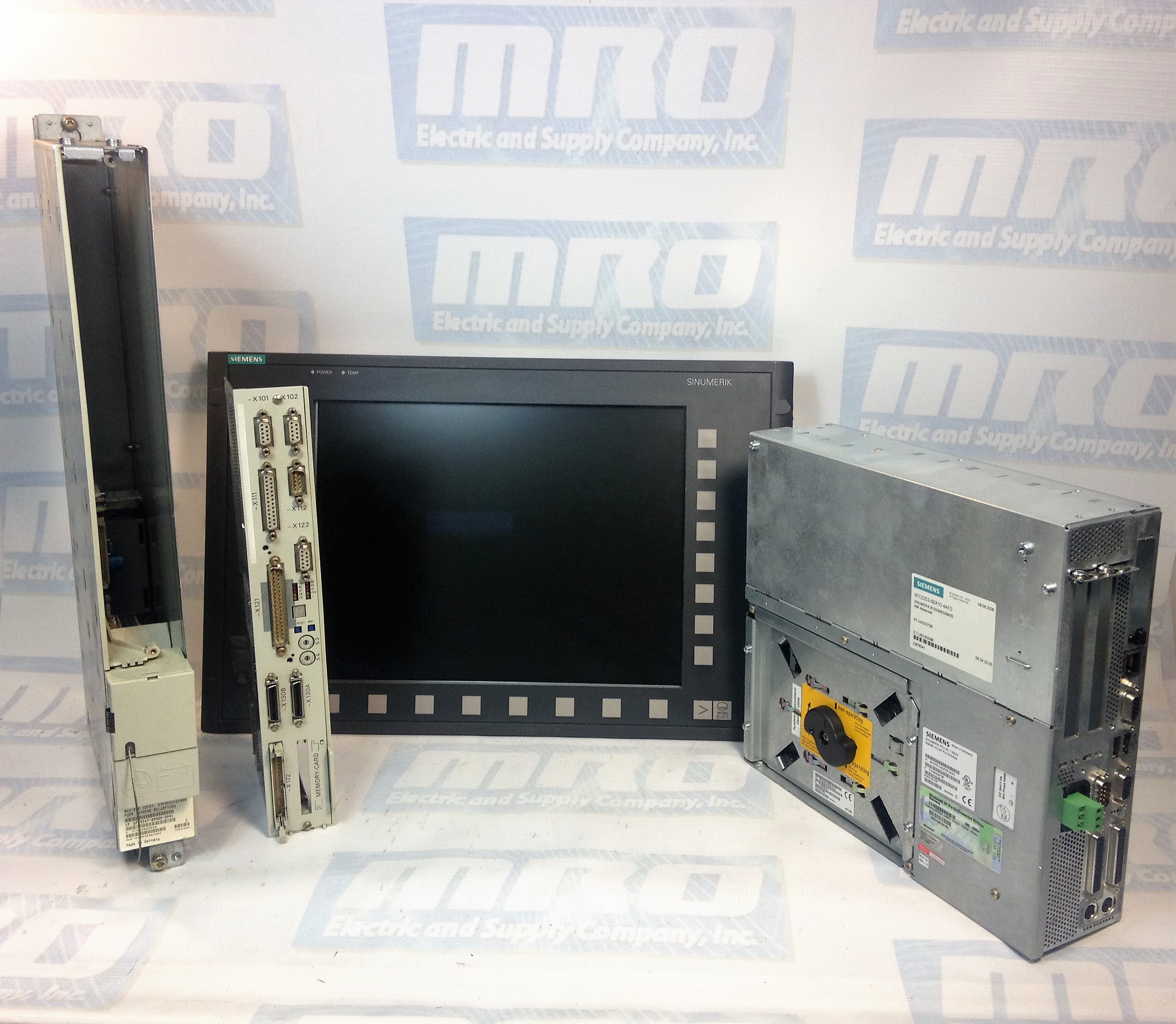
sinumerik 840d sl

Siemens SINUMERIK 840D SL: Product Spotlight & Alarms

The Siemens SINUMERIK 840D sl is a popular open CNC for modular and premium machining concepts with powerful and dynamic system functions that can be used for a wide range of applications. The CNC system is drive based, and can handle up to 93 axes or spindles and any number of PLC axes. The 840D sl can be used in combination with SINAMICS S120 drives and SIMATIC S7-300 PLCs. The system’s powerful hardware architecture and intelligent control systems ensure machining with the highest level of performance and precision. Additionally, there are a number of solutions that allow for easy IT integration.

The SINUMERIK 840D sl can be used for a wide range of applications including:

  • Turning
  • Milling
  • Gear Machining
  • Grinding
  • Machining Composites
  • Handles and CNC Machining using Robots
  • Nibbling, Waterjet Cutting, Laser Machining, & Plasma Machining
  • Multitasking

The SINUMERIK 840D sl has extremely high precision and performance with accuracy up to 80-bits nano. Its dynamic feed forward control ensures that following error is completely compensated for. With its superb algorithms such as Look Ahead, this system can perform at maximum speed with the same level of performance. The SINUMERIK system also minimizes idle time to keep your production levels at maximum capacity. It can handle kinematic transformations with ease, and sets the standard in energy efficiency. The SINUMERIK 840D sl has a number of integrated safety functions to protect personnel and other machines.

Below is the Siemens SINUMERIK Alarm List:

400000PLC STOP %1 Definitions: PLC not in cyclic mode. Travel with the machine is not possible. %1: 1 Ready(User program has not been started) 2 Break (User program has been interrupted) 3 Error (Other PLC alarm with PLC Stop active) Reaction: Alarm display. Remedy: Rectify other PLC alarm; Switch on menu in PLC stop position or test user program. Program Continuation: Alarm display showing cause of alarm disappears. No further operator action necessary.
400001System error %2 Definitions: %1 :Type number With this alarm, internal alarm states are displayed that, in conjunction with the transferred error number, provide information on the cause and location of the error. Reaction: PLC Stop Remedy: Notify Siemens of this error together with the error message. Program Continuation: Switch control OFF – ON.
400002System error %1 Definitions: %1 :Type number Internal error states are displayed with this alarm. An error number is also specified to provide further details about the cause and location of the error. Reaction: PLC Stop Remedy: Report this error to Siemens along with the type number. Program Continuation: Switch control OFF – ON.
400003Faulty connection to the operator panel Definitions: %1 :Type number This alarm displays that the connection to the machine control panel via the MCPA module has been interrupted. Reaction: Mode group not ready for operation Remedy: Check connection to the MCPA module. Program Continuation: Clear alarm with the Delete key or NC START.
400004Code error: %2 network %1 Definitions: %1 :Network number %2 :Internal error code, module type The user program contains an operation which is not supported by the control. Reaction: PLC Stop Remedy: Modify and reload user program. Program Continuation: Switch control OFF – ON.
400006Loss of remanent PLC data Definitions: The following causes are possible: Control handling (e.g. standard PLC deletion, power up with default values) Control handling of power up with backed up data without backing up data in advance Support time exceeded Reaction: Alarm display. Remedy: Update the data required. Program Continuation: Clear alarm with the Delete key or NC START.
400007Operand error: %2 network %1 Definitions: %1 :Network number %2 :Module type Reaction: PLC Stop Remedy: The variable displayed must be checked in the user program for violation of the address range, impermissible data type and alignment errors. Program Continuation: Switch control OFF – ON.
400008Programming tool – version is not compatible %1 %2 Definitions: %1 :Programming tool version This version is not compatible with the product version of the control system. Reaction: PLC Stop Remedy: Translate the user program using a suitable programming tool version and load in the control. Program Continuation: Switch control OFF – ON.
400009Computing time overrun at PLC level: %2 network %1 Definitions: %1 :Network number %2 :Module type Check user program of the corresponding network displayed. Reaction: PLC Stop Remedy: Change user program Program Continuation: Switch control OFF – ON.
400010Arithmetic error in user program: Type %2 network %1 Definitions: Check user program in the specified network. %1Network number, module ID %2 = 1:Division by zero using fixed-point arithmetic 2:Floating-point arithmetic Reaction: PLC Stop Remedy: Change user program. Program Continuation: Switch control OFF – ON.
400011Maximum number of subroutine levels exceeded: %2 network %1 Definitions: %1Network number %2Module ID Check user program in the specified network. Reaction: PLC Stop Remedy: Change user program. Program Continuation: Switch control OFF – ON.
400013PLC user program is incorrect Definitions: The PLC user program in the control is incorrect or is not available. Reaction: PLC Stop Remedy: Reload PLC user program. Program Continuation: Switch control OFF – ON.
400014PROFIBUS DP: power up interrupted, type: %1 Definitions: %1: 1PROFIBUS DP power up interrupted 2Software versions of NC and PLC do not match 3Number of slots per function exceeded 4PROFIBUS DP server not ready Reaction: PLC Stop Remedy: Types 1 to 3:Report error to Siemens Type 4:802D sl – Check and/or replace PCU hardware and/or check MD 11240 Program Continuation: Switch control OFF – ON.
400015PROFIBUS DP: I/O defect: log adr. %1 bus/station: %2 Definitions: The PLC-AWP is using I/O addresses which are not available. %1Logical I/O address %2Bus number/station number Causes of error: Bus peripheral has no voltage Bus address set incorrectly Bus connection faulty Active MD 11240 (SDB configuration) is set incorrectly Reaction: PLC Stop Remedy: Rectify the error using the error cause Program Continuation: Switch control OFF – ON.

The SINUMERIK 840D sl can be used in many different industries. Its customization solutions allow it to fulfill the requirements of even highly regulated industries. There are even support services and solutions provided for specific niches.
SINUMERIK 840D SL Applicatons

MRO Electric offers a variety of support services for the SINUMERIK 840D sl. These include providing new spares, refurbished components, and repair services. If you are in need of a replacement part or FANUC repairs, please call us at 800-691-8511 or email sales@mroelectric.com.
140CPU43412A Error Codes and Hot Standby

Our previous blog post on the 140CPU43412A describes the 140CPU43412A Configuration and Setup. 

140CPU43412A Hot Standby

You cannot create a Quantum Hot Standby configuration running one 140CPU53414A PLC with Unity firmware and one with NxT firmware. When using an NxT configuration in hot standby, both PLCs must have NxT firmware. When using a Unity Quantum hot standby configuration, only specific hot standby controllers can be used. The 140CPU43412A and 140CPU53414A PLCs are not supported in Unity Hot Standby configurations.

140CPU43412A Error Codes

The following are the error codes for the 140CPU43412A:

140CPU43412A Error Codes

140CPU43412A Error Codes

140CPU43412A Error Codes

For ordering info or for a 140CPU43412A price quote you can call 1-800-691-8511 or email sales@mroelectric.com.

140CPU43412A Firmware Part II

Phase 1 of firmware restoration is described in our previous blog post on the 140CPU43412A firmware.

140CPU43412A Firmware Part II

Restoring a 140CPU43412U (Unity) to 140CPU43412A (Concept):

Phase 2

During the download:

• Do not power OFF the PLC

• Do not power OFF the PC

• Do not disconnect the cable

• Do not shut down OS loader

Any loss of communication during the update procedure can cause severe damage to the CPU or NOE module. Failure to follow these instructions can result in injury or equipment damage.

Reset the PLC

Once the download of the intermediate binary file has completed, the PLC has to be initialized. This task can be performed by one of the two following actions:  Reset the PLC by pushing on the Restart button located on the CPU (for more information, refer to the PLC technical documentation).  Power OFF then ON the PLC. Once the PLC has restarted, go to Phase 3: download the final Concept OS.

Phase 3

Presentation

The final binary file “q5rv135E.bin ” (140CPU34312 in our example) has to be downloaded. For that, follow the same procedure as the one described in the Phase 1.

Checking Version (optional)

If needed, you can check the new CPU version. For that  Open the OS loader tool.  Select the communication protocol.  Click on “Connect.” Then Click on “Properties.”

For ordering info or for a 140CPU43412A price quote you can call 1-800-691-8511 or email sales@mroelectric.com.

140CPU43412A
140CPU43412A FIrmware

140CPU43412A Firmware Part I

Click now to view our blog on the 140CPU43412A Configuration and Setup. 

140CPU43412A Firmware

The q5rv144e.bin file supports both Concept (IEC & 984) and ProWORX PLCs.

In order to restore a 140CPU43412U (Unity) to a 140CPU43412A (Concept), three main phases are required.

Phase 1 – Restore the PLC to Concept with an intermediate OS. 

Phase 2 – Power OFF then ON the PLC. 

Phase 3 – Restore the Operating System with the appropriate file.

These phases are mandatory and cannot be by-passed.

Phase 1: 

Launching the OS Loader

The OS loader (provided with Unity) allows the user to download the Operating System to the PLC. To open it click on Start/Program/SchneiderElectric/Unity-PRO/OS loader.

Select the Communication Protocol

From the main screen of the OS loader, click on the “Next” button. To download the Operating System into the PLC, select the right communication protocol (in accordance with established physical link) and click on the “Next” button.

Select the Target Device

On the Device Type field, select Processor and the other needed parameters (Modbus address….). Then connect to the selected PLC (Node).

Select the Download Function 

From the screen described above press the “Next” button. A new screen is proposed: select “Download OS to device”.

Select the File to be Downloaded

Click on the “Browse…” button in order to select the file to download into the PLC. In this example we will restore the OS from 140CPU43412U to 140CPU43412A firmware. For that select the following folders: Quantum\Processor_modules\Unity_to_Concept. To restore the OS from Unity to Concept, two binary files can be selected:  Unity_to_Concept_43412A.bin (allows to “format” the processor to Concept)  q5rv135E.bin is the OS that will finally be downloaded in the processor. In our example we have to “format” the processor (remember, we still are in the Phase 1) then select and Validate “Unity_to_Concept_43412A.bin”. Once done click on the “Next” button.

Download the Intermediate OS

Once the previous screen is validated a warning is displayed: Click the “Okay” button. Two screens that give information regarding the file, the processor and the download are now displayed. Note: If the system detects a discrepancy on the hardware or on the OS version, the download will not be possible. This is indicated by a red cross and the “Next” button becomes unavailable. Solve this issue and continue. When the hardware – OS are compatible, click on the “Download” button to launch the download of the intermediate OS file.

Click Now for 140CPU43412A Firmware  Restoration Phases 2 & 3

For ordering info or for a 140CPU43412A price quote you can call 1-800-691-8511 or email sales@mroelectric.com.

140CPU43412A
140CPU43412A Firmware

Siemens Sinumerik Drive and I/O Alarms

For troubleshooting your Siemens Sinumerik system, here is a list of the Siemens Sinumerik Drive and I/O Alarms directly from the Sinumerik manual. For more info, give us a call at 800-691-8511 or email sales@mroelectric. Our full Sinumerik series is listed here.

Drive and I/O alarms

Alarms

334 Diagnostics Manual, 03/2011, 6FC5398-2CP10-3BA0

300411 Axis %1 drive %2 error when reading a file (%3, %4)

Parameters: %1 = NC axis number

%2 = Drive number

%3 = Error code 1

%4 = Error code 2
Read More