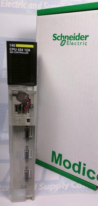
You can check out our previous blog post on the 140CPU43412A manual and configuration here for additional setup info.
Front Panel Topology
Rear Panel Topology
The address switch, which is comprised of two rotary switches, is located on the rear panel of the Quantum CPUs. The address switch is used for setting Modbus Plus node and Modbus port addresses. SW1 (the top switch) sets the upper digit (tens) of the address, SW2 (the bottom switch) sets the lower digit (ones) of the address. The illustration below shows the correct setting for an example address of 11.
Option Module Interface Support
The 140CPU43412A firmware supports up to six network modules (i.e., Modbus Plus, Ethernet, and Multi-Axis Motion option modules) using the option module interface technique. However, only two Modbus Plus modules can have full functionality, including Quantum DIO support.
For ordering info or for the 140CPU43412A price you can call 1-800-691-8511 or email sales@mroelectric.com.

Updated on March 5, 2020 by Brian Hughes
