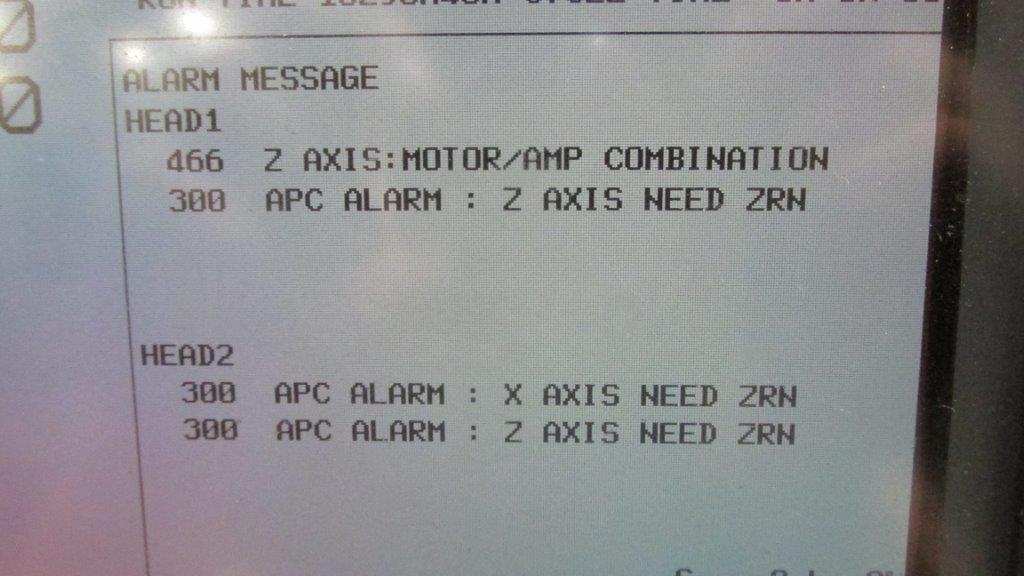
Fanuc Alarm 466 – Z Axis: Motor/Amp Combination

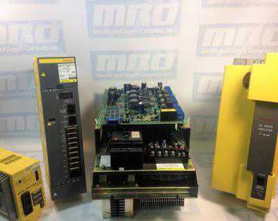
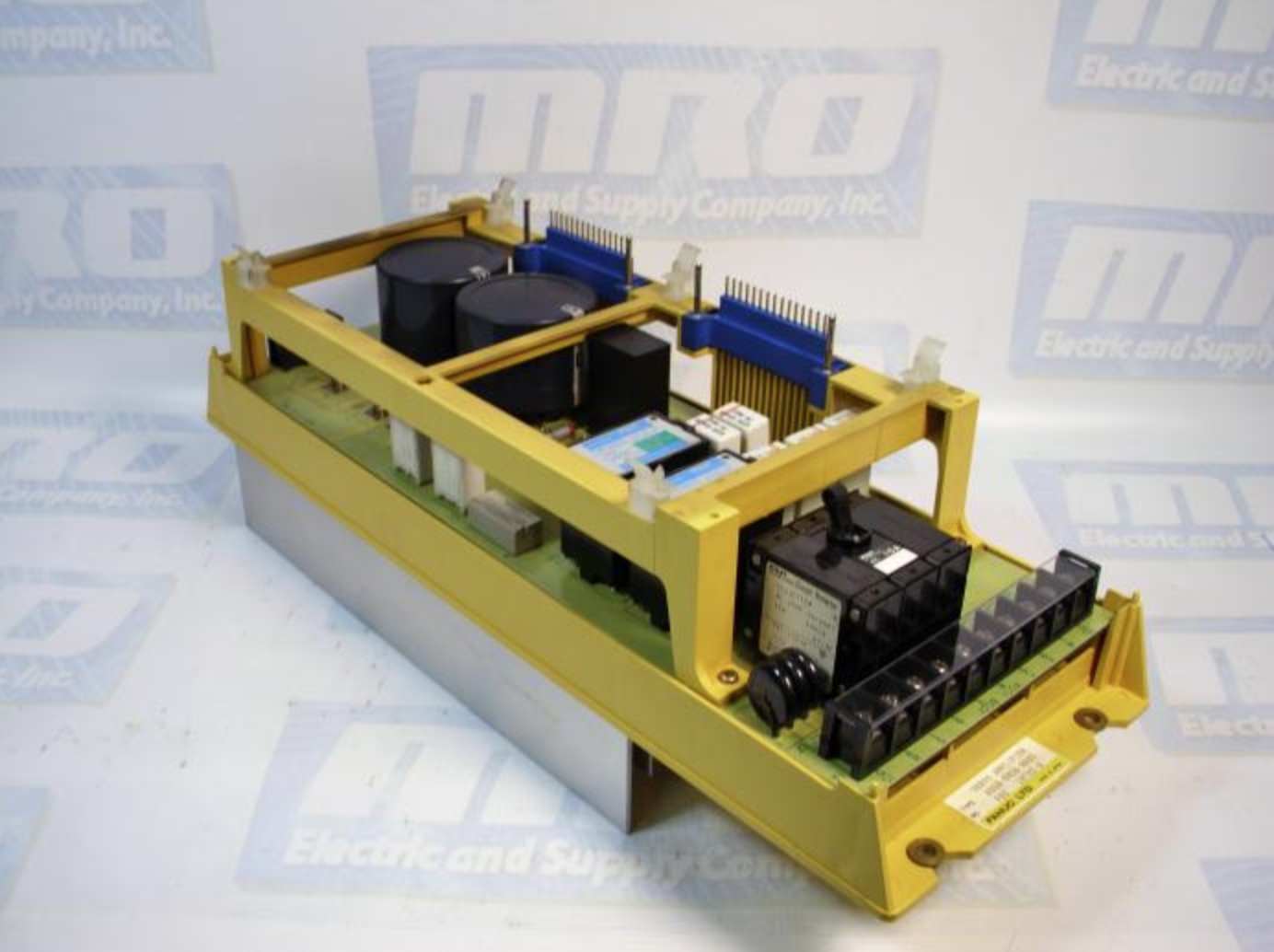
We just shipped out a Fanuc A06B-6096-H207 Servo Amp unit to a customer, and as soon as they installed the amplifier they got a Fanuc Alarm 466 which refers to the Z Axis: Motor/Amp Combination. This is obviously somewhat distressing for a customer to buy a replacement unit and immediately get an alarm when it is installed, but fortunately this is an easy fix.

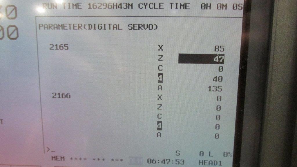
This Alarm 466 comes from the replacement amplifier having newer servo software than the unit that it is replacing. As Fanuc has made newer units they’ve upgraded the software/hardware within these amplifiers, so you just need to reset a parameter to reboot the configuration and clear the 466 Alarm. The steps are below.

– Put the machine in Emergency Stop
– Go to parameter 2165 on the control
– Set all the values to 0
– Take the machine out of emergency stop

Once these parameters are changed and the machine is rebooted, the alarm will clear and the amplifier will initialize. We also have pictures below to confirm that you know what to look for. For any additional help, call us at 800-691-8511 or email sales@mroelectric.com.

FANUC Alarm 466
FANUC Alarm 466
FANUC Alarm 466
FANUC Alarm 466
MRO Electric stocks a large number of FANUC CNC Products, and provides repair services as well. For more information or to request a quote, please call 800-691-8511 or email sales@mroelectric.com.

Fanuc A06B-0075-B503 Motor Product Video

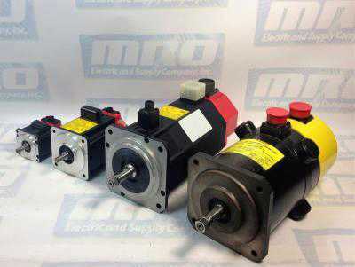
Here is a video of one of the many Fanuc AC motors that we have in stock,  and this one is the Fanuc A06B-0075-B503 Motor. This is an AC Fanuc motor that has a brake and a keyway already installed. At 22.85lbs and 8.1 X 15.3 X 6.5 inches, this is one of the smaller motors that Fanuc manufactures. The motor in the video is brand new and comes in the original factory packaging, we only took it out of the packaging to get a video of it. If you are looking to get your old motor repaired, we do also offer a repair service for these AC motors with a standard turnaround of 3-5 days.

If you’re also trying to figure out if your motor is bad you can check out this other blog post that we put up to show some basic steps for testing your motor. The page is here, it has some useful steps to go through to confirm that your motor is causing your problem.

MRO Electric and Supply maintains a comprehensive stock of new and used FANUC CNC and FANUC Robots parts. If you need a FANUC replacement part, please call 800-691-8511 or email sales@mroelectric.com.

Product Video – Fanuc A06B-6066-H008 Servo Amp

To highlight some of the products that we have in stock and service we’ve decided to start uploading videos of the individual products. Here is a look at the Fanuc A06B-6066-H008 Servo Amp that we have in stock. The unit has been recently refurbished, is fully tested and is ready to ship out today if need be. We also offer repair on these servo amplifier units with a standard turnaround of 3-5 days.

Be sure to check out our article covering FANUC CNC Troubleshooting Frequently Asked Questions here.

MRO Electric and Supply maintains a comprehensive stock of new and used FANUC CNC and FANUC Robots parts. If you need a FANUC replacement part, please call 800-691-8511 or email sales@mroelectric.com.

Fanuc Spindle Amp Alarm Codes for Alpha Series

fanuc spindle amp

Fanuc Spindle Amp Alarm Codes for Alpha Series

Fanuc Spindle Amp Alarm codes for amplifiers that start with part number A06B-6088, A06B-6102, and A06B-6078.

“A” Program Rom abnormality (Not Installed)

AL-01 Motor Overheat

AL-02 Excessive speed deviation

AL-03 DC Link fuse blown

AL-04 Input fuse blown

AL-05 Control power supply

AL-06 Over Speed

AL-07 Excessive Speed

AL-08 High Input Voltage

AL-09 Excessive load on main circuit section

AL-10 Low input voltage

AL-11 Over-voltage in DC link section

AL-12 Over-current in DC link section

AL-13 CPU Internal data memory abnormality

AL-15 Spindle switch/output switch alarm

AL-16 RAM Abnormality

AL-18 Program ROM checksum error

AL-19 Excessive U phase current detection circuit offset

AL-20 Excessive V phase current detection circuit offset

AL-24 Serial transfer data error

AL-25 Serial transfer data stopped

MRO Electric and Supply maintains a comprehensive stock of new and used FANUC CNC parts including FANUC Spindle Amps. If you need a replacement part, please call 800-691-8511 or email sales@mroelectric.com.

AL-26 Disconnection of speed detection signal for C’s contouring control

AL-27 Position coder signal disconnection

AL-28 Disconnection of position detection signals for C’s contouring control

AL-29 Short-time overload

AL-30 Input circuit over current

AL-31 Speed detection signal disconnection motor restraint alarm

AL-32 Abnormality in RAM internal to LSI for serial data transfer

AL-33 Insufficient DC link section charging

AL-34 Parameter data setting beyond allowable range of values

AL-35 Excessive gear ratio data setting

AL-36 Error counter overflow

AL-37 Speed detector parameter setting error

AL-39 Alarm for indicating failure in detecting 1-rotation signal for C’s contouring control

AL-40 Alarm for indicating 1-rotation signal for C’s contouring control not detected

AL-41 Alarm for indicating failure in detecting position coder 1-rotation signal

AL-42 Alarm for indication position coder 1-rotation not detected

AL-43 Alarm for indicating disconnection of position coder signal for differential speed mode

AL-46 Alarm for indicating failure in detecting position coder 1 rotation signal in thread cutting operation

AL-47 Position coder signal abnormality

AL-48 Position coder 1-rotation signal abnormality

AL-49 The converted differential speed is too high

AL-50 Excessive speed command calculation value in spindle synchronization control

AL-51 Under voltage at DC link section

AL-52 ITP signal abnormality 1

AL-53 ITP signal abnormality 2

AL-54 Overload current alarm

AL-55 Power line abnormality in spindle switching/output switching

AL-56 Cooling fan error.

How to Troubleshoot Faults of Fanuc Alpha Servo Drives

fanuc cnc

What is a FANUC Servo Alarm 8, 9, or A?

Before we dive in, let’s discuss what exactly a FANUC servo alarm is.

When a Fanuc Alpha Servo drive shows an A, 9, or 8 alarm, this is indicative of a short circuit or high current in the motor or amplifier. To fix this, you must determine which axis is at fault. Make sure you’ve checked this is not a mechanical failure or even a binding condition beforehand.

The alarm will point to this area:

  • FANUC servo drive alarm 8 is the L axis
  • FANUC servo drive alarm 9 is the M axis
  • FANUC servo drive alarm A is the N axis

Troubleshooting FANUC Servo Alarm 8,9, or A

This troubleshooting guide is in reference to Fanuc drives that begin with part number A06B-6079, A06B-6080, and A06B-6096 and is meant to help troubleshoot Fanuc servo amplifiers faults. Before you continue to determine what’s happening to your servo amp, make sure to check for the following:

1 – Determine if your servo amp or motor is defective.

If the alarm is occurring before the motor power is present, consider checking either the servo amp or the feedback circuit. Do this by disconnecting the feedback cable and turning on the power. This will isolate the failure. If you have no alarm, this means the problem lies with the feedback cable or a pulse coder. If the fault remains, the servo amp is the issue.

If the alarm does not occur before motor power, then you will need to continue following the below steps.

If the alarm occurs when motor power is present, the problem might lie with the motor power circuit or the servo amplifier. Disconnect the power cable and turn the machine on. If this action results in the alarm continuing, the problem is with the servo amp. If this action ceases the alarm, follow the next steps.

2 – Shut off the power

Never forget safety when working with these devices. For the proceeding steps, make sure to disconnect the servo amplifier. Also keep in mind, if a drive status alarm appears on the 7 segment display, where the “-” refers to drive not ready (Waiting for an Emergency Stop signal to power up) and “0” refers to drive powering up correctly. Any other number or letter on this status display is one of the FANUC alarm codes. This is one of the more common faults, the FANUC servo Alarm 8.

Here are the steps to check to see what the issue may be when an alarm comes up on your drive.

FANUC Alarm Code 8, 9, or A Steps

1 – Check the link

(A06B-6079 drives only). An A06B-6079 drive can give a fault if the S1 Link is in the wrong position, so check the S1 – JV Connections (Type A Interface) and S2 – JS Connections (Type B Interface). An incorrect setting will cause a FANUC Drive Alarm “8”.

2 – Check the wiring

A L motor is wired in the lower terminals and an M motor is wired in the upper terminals, both as U/V/W/E. JV1B connected from the L command plug of the axis card, JV2B from the M command plug. JX1A connected from previous drive, JX1B connected to the next drive in the line. The last drive in the line has a terminator in JX1B. 24v/0v/ESP connected into CX1A from the previous drive, out of CX1B to the next drive in the line.

3 – Disconnect motor cable

Meggar the motor to check the readings.

4 – Power machine on

Do this while it is in an emergency stop. The drive is faulty if an alarm occurs, expect a “-” reading.

5 – Release Emergency Stop

Power the machine up after releasing the stop. If an alarm occurs, power the machine off and remove motor wires U/V/W/E (Note – this is dangerous on a vertical axis, brake release, slide drops etc). Release Emergency Stop and power the machine up. The drive is faulty if the alarm occurs, expect “0” reading.

Alternative Options

If these steps do not help, an additional test can be performed for equally sized 6079/6080 amplifiers H201 SVM2-12/12          H301 SVM2-12/12/12 H203 SVM2-20/20          H302 SVM3-12/12/20 (L&M) H206 SVM2-40/40          H303 SVM3-12/20/20 (M&N) H208 SVM2-80/80          H304 SVM3-20/20/20 (L/M&N) The suspect axis can be run from the other amplifier in the drive ie X drives M amplifier, Y drives L amplifier. To do this swap round a – X & Y Motor cables U/V/W/E (at the drive) and b – X & Y Command cables (at the drive) (6096 requires parameters changing to swap X & Y round).

The drive is faulty if the alarm remains the same as before the test. For example Alarm “8” is reported on a 6079-H201 drive using JV connections Steps 1~5 above, have been performed and still alarm “8”. Remove the servo motor wires from the lower terminals and reconnect into the upper terminals, upper into lower. Remove JV1B and insert into JV2B, JV2B into JV1B. Retest the machine.

The drive is faulty if the same alarm occurs, ie alarm “8” The fault lies elsewhere on the machine if another alarm occurs, ie alarm “9”. In this example the drive has detected an overcurrent from the L axis, alarm “8” Swapping the cables over allowed a different amplifier to control the axis. An “8” alarm would remain if the same drive circuitry detected the overcurrent. A “9” would occur if the overcurrent was detected using the other drive circuitry in the amplifier and the fault would be caused externally from the drive.

Still having trouble with your Fanuc Servo Alarm 8, 9, or A?

Contact MRO Electric for help. Get yourself a new FANUC servo amplifier or check out our FANUC servo motors. MRO Electric and Supply supplies and repairs a large number of FANUC Servo Drives. To request a quote, please call 800-691-8511 or email sales@mroelectric.com.
Troubleshooting Fanuc Servo Devices

A06B-6058-H005

Troubleshooting Fanuc Servo Devices

Recently we had a customer that we helped with troubleshooting a FANUC servo A20B-1003-0090 board that he was installing into an A06B-6058-H005 drive. A handful FANUC troubleshooting options are listed below.

Troubleshooting for the DCAI alarm:

[check items]

  1. Setting S2 for the S series
  2. Machine load
  3. Check connection of separate discharge unit

[Adjustment procedure]

A. Check amplifier setting S2. If the setting is incorrect, go to Cause 1. If the setting is correct, go to A-0.

A-0: Check whether a separate discharge unit is being used. If it is being used, go to A-1. If not being used, go to A-2.

A-1: Check the connection of the separate discharge unit. If the connection is incorrect, go to Cause 2. If connection is correct, go to A-2.

A-2: Check the acceleration/deceleration frequency. If the frequency is too high, go to Cause 3. If the frequency is low enough, go to A-3.

A-3: Replace the servo amplifier. If a DCAL alarm no longer occurs, go to Cause 4. If a DCAL alarm still occurs, go to Cause 3.

[Causes]

1). If the setting S2 of the S series servo amplifier is incorrect, a DC alarm is caused.

2). If the separate discharge unit is connected incorrectly, a DC alarm occurs.

3). Compared to the regenerative power of the amplifier, the regenerative energy of the motor is too large. (The inertia is too large or the acceleration/deceleration frequency is too high.) In this case, try to decrease the acceleration/deceleration frequency or install a separate discharge unit.

4). The discharge transistor (Q1) in the servo amplifier is defective.

MRO Electric and Supply has new and refurbished FANUC CNC products available, including FANUC Servo parts. We also offer repair pricing. For more information, please call 800-691-8511 or email sales@mroelectric.com.