How Variable Frequency Drives (VFDs) Work: Unveiling the Magic of Precision Control

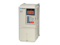
Variable Frequency Drives (VFDs) have become ubiquitous in the world of industrial automation and energy management. They are remarkable devices that play a crucial role in regulating the speed and efficiency of electric motors. Whether you’re a seasoned engineer or just a curious enthusiast, understanding how VFDs work can empower you with valuable knowledge about the heart of modern manufacturing processes and energy-efficient systems. In this comprehensive guide, we will explore the inner workings of VFDs, from their basic principles to their applications in various industries.

The Basics of VFDs

At its core, a Variable Frequency Drive is an electronic device designed to control the frequency and voltage supplied to an AC (Alternating Current) motor. By altering these two key parameters, VFDs can precisely manipulate the motor’s speed, allowing it to operate at varying speeds with incredible precision. This fundamental capability finds applications across numerous industries, from HVAC (Heating, Ventilation, and Air Conditioning) systems to manufacturing processes, where precise control of motor speed is essential.

Schneider Electric Altivar Variable Speed Drive

Frequency Control

The heart of VFD operation is the ability to control the motor’s frequency. In an AC motor, the speed is directly proportional to the frequency of the supplied power. Standard power from the grid operates at a fixed frequency (usually 60 Hz in North America and 50 Hz in most other regions), resulting in a constant motor speed when connected directly. However, VFDs can modify this frequency according to the desired speed, creating a dynamic system.

To adjust the frequency, VFDs convert incoming AC power into DC (Direct Current) using rectifiers, then generate a new AC output with a variable frequency through an inverter. This allows precise control over the motor’s rotational speed, ensuring it operates optimally under varying conditions.

Read More

Mastering CNC Maintenance: 15 Essential Tips for Peak Performance

Computer Numerical Control (CNC) machines are essential tools in modern manufacturing and machining. These precision instruments can perform complex tasks with incredible accuracy. However, like any machinery, CNC machines require regular maintenance to ensure they operate efficiently and reliably. In this comprehensive guide, we’ll explore 15 essential tips for CNC maintenance to keep your equipment in optimal condition.

Chapter 1: Daily Maintenance

  1. Cleanliness is Crucial Maintaining a clean CNC machine is paramount. Dust, chips, and debris can lead to performance issues and wear on critical components.
    • Start each day by blowing away chips and dust with compressed air.
    • Wipe down surfaces with a clean, lint-free cloth.
    • Ensure that coolant and lubrication systems are clean and free from contamination.
  2. Inspect Toolholders and Workholding Devices Check toolholders, collets, and workholding devices daily for signs of damage or wear. Replace any components that appear compromised to maintain precise tool alignment.
  3. Lubrication Most CNC machines require regular lubrication. Refer to the manufacturer’s manual for a lubrication schedule and be precise in your application. Over- or under-lubrication can lead to problems.

Chapter 2: Weekly Maintenance

  1. Examine Way Covers and Bellows Way covers and bellows protect critical machine components from contaminants. Inspect them weekly for damage or leaks and replace any compromised parts to prevent issues.
  2. Spindle and Taper Maintenance Clean the spindle and taper thoroughly, removing debris or buildup. Inspect for wear and have them professionally serviced or replaced if necessary.
  3. Check Electrical Connections Regularly inspect all electrical connections, wires, cables, and connectors for wear or loose connections. Reliable electrical connections are crucial for CNC machine performance and safety.
Read More

Yaskawa Drive Types

Yaskawa

Yaskawa Electric is a global manufacturer of high-quality parts used in robotics and automation. They specialize in servos, controllers, switches, robots, drives and more. These parts are used for a variety of purposes in industry. In this post, we will be distinguishing the different types of Yaskawa drives.

CIMR Drives
E7 Drives– Designed for commercial HVAC applications. Embedded with Modbus, APOGEE FLN and Metasys N2.
F7 Drives– Well-rounded drive with a variety of uses. Contains NEMA Type 12 enclosure with space to expand filters, fuses, I/O cards and more.
G7 Drives– Low voltage drive that uses 3 level control to combat problems with long motor cables and premature motor bearing failure. Great vector performance and flexibility. Configured options with pre-engineered cabinet options available.
P7 Drives– Created for applications with variable torque like centrifugal pumps and fans.

yaskawa p7

GPD Drives
GPD 333– General purpose AC Drive, 1/4 the size of normal PWM drives.
GPD 503/505/506– High-performance three phase voltage/frequency output with adjustable speed control.
GPD 515– PWM AC drive designed for low motor noise and high starting torque.

Microdrives
J1000 Drives– General purpose drives with open loop voltage/frequency control with preferred parameter feature. Simple variable speed of up to 7.5HP.
V1000 Drives– Compact current vector drive designed for efficiency and maintainability. Capable of up to 25HP. Economical for basic variable speed applications.
V1000-4X Drive- The same as the V1000 but with an enclosure built for dust tight environments.

Other Drives
A1000 Drives – High performance general purpose drive capable of up to 1000HP. Used for general purposes.
P1000 Drives – Torque performance capable of withstanding 1000HP. Oriented towards variable torque applications including centrifugal pumps and fans. Configured and bypass options available.
U1000 Industrial Matrix Drives – Regenerative high performance vector drive capable of up to 800HP. Used for general purposes.

Source: https://www.yaskawa.com/

Visit MRO Electric and Supply’s website to see all of our available Yaskawa Drives. If we don’t have what you need listed on the site, contact us at sales@mroelectric.com or (800) 691-8511 and we will be happy to help!

Yaskawa SIGMA 5 Troubleshooting

Yaskawa has established a firm position as the leading international developer of servo products in recent years, surpassing its competitors with innovation and utilization of advanced modern technologies.

Its Sigma 5 series is absolutely top of the class! Incorporated with the latest and most desirable features, this fleet of servo products does not disappoint. The Sigma 5 series catalog is briefly over-viewed below.

  • SERVOPACKs is a series consisting of high-end networkable amplifiers that support motors up to 55 kW
  • Rotary Servo Motors with outputs in the wide range of 50W – 15kW
  • Direct Drive Servomotors with peak torque 6-600 Nm
  • Linear Servomotors are directly driven by a coil
  • Linear Slides complete the package for customers using linear servomotors, comprising of components such as slides, carriages, etc.

With such a versatile range of products, Sigma 5 series is easily what you would want to have in your workshops and industries.

SGMGV-09ADA61

All servo drives are tailored according to contemporary market demands. With so many different kinds of motors, the drives make use of complex algorithms that allow engineers to exercise precise control over the motor output, helping them achieve the accuracy modern applications require.

Yaskawa is highly regarded among consumers and the industry for its professionalism. From product development to customer dealing, this quality shows through at each stage, and this is exactly what puts this company at the top.

This blog is dedicated to one aspect of this characteristic: Troubleshooting. Sigma 5 series is undoubtedly the most functional of all but this also means that the intricacies involved can sometimes be difficult to handle.

If one of these products does not perform as it should be, troubleshooting it should be something that field engineers should be able to do. Thankfully, the Sigma 5 series is accompanied by clear troubleshooting guidelines and is one of the most easy to handle.

  • Product Documentation

Each product comes with comprehensive documentation that can be accessed at any time to gain in-depth knowledge of its working. These documents contain important information like dedicated troubleshooting guides, operating parameter, alarm lists, product structure, and specifications.

With this information at hand, troubleshooting any of the Sigma 5 products becomes a piece of cake!

  • Software Support

Sigma 5 series comes with a very supportive software suite as well which can serve as the perfect troubleshooting tool. During installation and operation, these software used extensively for product setup and configuration.

The SigmaWin+ is an intuitive tool that allows convenient setup of each servo product. If you observe anything out of the normal with your Sigma 5 products, the first thing to do would be to check whether the configuration settings are compatible with your application.

Its most helpful function is the alarm diagnostic function. Troubleshooting is usually initiated after a machine raises an alarm. This software is designed to identify all the possible reasons that might have generated a specific alarm, and presents possible corrective measures as well.

Moreover, SigmaWin+ has enhanced features such as wiring check and auto-tuning of multiple parameters. Using these you can not only find the loopholes you are looking for but also optimize operations.

  • Yaskawa Customer Support

To top off the aforementioned troubleshooting options, MRO’s Repair team is always available for help. If you are experiencing a mind-boggling issue with your Sigma 5 products, this team is the go-to. Apart from repair work, MRO Electric and Supply has a core exchange program that saves the buyer time and money when receiving their new unit.

ATS48 Soft Start Troubleshooting and Introduction

The Altistart 48(ATS48) series of soft starters by Square D and Schneider Electric allows for consistent start/stop rates that are independent of motor loads. These devices are more advanced than the standard drives that cannot control the applied motor torque. Featuring contact wiring and control, the soft starter allows for near-seamless integration with existing operations. Many preset parameters are included with the device and they cover a large spectrum of operations. Additional parameters may also be loaded up to meet specific needs. Available power ratings include:

  • 3 – 200 HP @ 208VAC, 60 Hz
  • 5 – 250 HP @ 230VAC, 60 Hz
  • 10 – 500 HP @ 460VAC, 60 Hz
  • 15 – 600 HP @ 575VAC, 60Hz

The ATS48 series features a dual configuration of two motors which allows for a cascaded start/stop in many operations. Using the Torque Control System(TCS) the unit can minimize wear on gears which allows for less time servicing the unit.

The Altistart 48 series takes advantage of the PowerSuite™ software for programming of your drive or soft starter.  With this software, you will be able to monitor and document all of your operations. Configurations are easily saved via hard disk, CD-ROM, flash memory, etc. Using Ethernet technology, the user is able to configure and monitor operations on the go, and a constant feed of information allows for real-time opportunity to modify and adjust configuration files on the fly.

Troubleshooting can be an issue for people when so many different things are going on. It just isn’t feasible to stop operations every time an error occurs. Below is a list of fault codes for the ATS48 Soft Start series that will help determine most issues:

Fault CodeDescription
nLP
rdY
Soft start without run command and:
• Line power not supplied
• Line power supplied
tbSStarting time delay not elapsed
HEAMotor preheating in progress
(Use SUP menu to set up monitoring
parameter. Factory setting: Motor Current.)
Soft start with run command
brLSoft start braking
StbWaiting for a command (RUN or STOP) in
cascade mode
CFF Invalid configuration on power-up
CFI Invalid configuration
CLFLoss of Control Power
EEFInternal memory fault
EtFExternal fault
ErFLine frequency out of tolerance
InFInternal fault
LrFLocked rotor fault
OCFOvercurrent fault
OHFSoft start overheating fault
OLCCurrent overload fault
OLFMotor overload/ground fault
OtFMotor thermal fault detected by PTC probes
PHFLoss of line or motor phase
PIFPhase reversal fault
SLFSerial link fault
StFExcessive starting time
ULFMotor underload fault
USFLack of AC line power on a run command

MRO Electric and Supply carries all models of this unit and has a fast and easy repair service to get your unit fixed and back into your hands as soon as possible.

Struggling with your ATS48 Soft Starter?

MRO Electric provides the insights and assistance you need to troubleshoot efficiently. Our inventory is stocked with the necessary parts, and our experts are on standby to help you minimize downtime.

Determining if your FANUC Motor has a Keyway

There are a couple ways to figure out if your FANUC motor has a keyway:

The first is if you can visibly look at the end of the shaft and see the holes on the end of the coupling. If your shaft has one hole at the end in the very center, it is a slick shaft. If the shaft has three holes in a line, that means you have a keyed shaft.

Another way to check if you have a keyed shaft without being able to look at the shaft is reading the OEM label on the FANUC motor. Your motor may have one of two types of labels on it, the first being a yellow FANUC sticker and the other being a silver G.E. FANUC sticker. All of the silver G.E. FANUC stickers on motors have a # suffix indicating a keyed shaft, except for the tag #7000 which indicates that it is actually a slick shaft. The pictures below show what each tag looks like with the # tag.

ge-fanuc

fanuc

The yellow FANUC sticker is a little bit easier to determine. If the part number has the # tag at the end of it, it is a keyed shaft. If there is no # at the end of the part number, that means it is a slick shaft. Below is a picture of a yellow FANUC tag without the # tag.

keyed-shaft

Be sure to check out our article focused on maintaining automation machine tools. Maintenance is unavoidable and compiling maintenance with unnecessary rebuilds is unpractical and will likely result in downtime and lost profit. We also offer top quality repair services on all drives. With a 100% guarantee 12-month warranty we will ensure you are happy with your decision to repair with MRO Electric.

MRO Electric and Supply has new and refurbished FANUC CNC parts available. We also offer repair pricing. For more information, please call 800-691-8511 or email sales@mroelectric.com.

FANUC Alarm Codes – A06B-6066 Drives – Alarm 5

The following is a list of procedures to fix the Alarm 5 status on your drive:

  • If you are receiving the alarm after a fresh install of the drive, check to make sure all jumpers and wires are set in their correct position. You can find the location for these inside your user manual.
  • Make sure the drive is off. Check the resistances on the drive, and then test the voltage. If it has been powered up recently, you can then turn it on to check the voltage again. However, do not immediately turn it back off to check the resistances again. You must give it at least 30 minutes for the voltage to return to safe levels so that you can check again.
  • To check the voltage, you can test the DC voltage of the jumper attached between screws 17/18 and 19.
  • Using your ground on screw 19 and and the red lead on the other two screws, your reader should say anywhere from .003 to .006 volts.
  • To check the resistance, remove the jumper from screws 15/16 and then tighten the screws. Use an ohm reader to make sure the resistance isn’t OPEN.
  • Check the resistance between screws 17 and 18. If it is 16 ohms that is where you want it to be.

fanuc cnc

Sometimes you may not have the necessary equipment to make a diagnosis on your motor, but we do. MRO Electric and Supply offers high quality repair services on all motors and spindle drives so you don’t have to worry about it. Please take a look at our website to see all available brands and parts we can service for you. Our rebuilds for these size drives usually only take 2-3 days, which includes rebuilding the part, painting the part, and fully testing the part to ensure top quality. By getting your part back to you as soon as possible, you are able to minimize downtime, and by doing the job right you can have peace of mind knowing that your FANUC drive will now work properly and not be the reason for downtime in the future.

MRO Electric and Supply has new and refurbished FANUC CNC parts available. For more information, please call 800-691-8511 or email sales@mroelectric.com.