Enhance System Performance with Modicon Quantum I/O Modules

Substation I/O modules for direct 125 Vdc control
Quantum I/O modules are available for direct connection to critical 125 Vdc battery powered equipment such as circuit breakers, protective relays, transformers and capacitor banks.

  • Built-in high transient noise immunity ensures reliable operation in harsh 125 V DC environments.
  • The 125 Vdc 30A high current output module eliminates expensive high current interposing relays used in breaker tripping and closure.
  • The solid-state 125 Vdc low current output module ensures long life and trouble-free operation in higher frequency 125 Vdc switching environments without the use of expensive external snubbing circuitry.
  • Over-current/ short circuit diagnostics and protection on all solid state 125 Vdc outputs reduce downtime by ensuring quick identifi- cation of circuit prob- lems and fast repair.

Latch/Interrupt module for time critical applications
The Quantum Latch/ Interrupt module is a multi-purpose high speed input, latch,
and interrupt module combined, which is configurable through programming software. Interrupt handling instructions are part of the 984 Ladder Logic instruction set. Quantum throughput performance for 2 interrupts is typically 1ms.
High speed counters don’t miss a pulse
Quantum high speed counter modules, such as the 140EHC10500, have the ability to count pulses at speeds much faster than the Quantum controller can directly do by itself. These modules automatically report the current count to the Quantum controller every scan.

Simple ASCII exchanges
The Quantum ASCII module is a general purpose ASCII interface that provides the ability to communicate and ex- change data with devices including printers, bar code readers and scanners, weigh scales, and meters. This module is designed for relatively simple point to point ASCII communications, with ASCII messages stored inside the module triggered by logic within the Quantum controller.
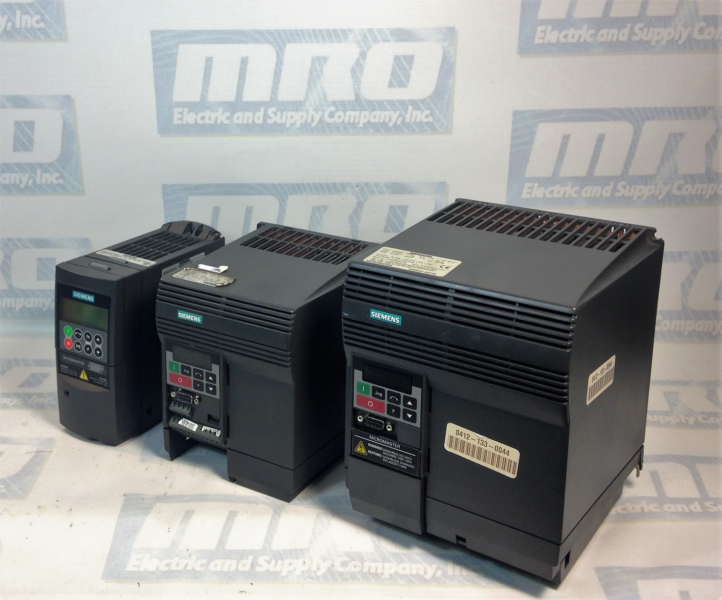
Micromaster 420

Siemens Micromaster 420 Troubleshooting Tips

Often people have difficulty installing a replacement drive that we send out, and normally it just takes the troubleshooting tips from the manual to get them up and running. However, the manual isn’t always the easiest to find or sort through, so below we’re posting the Siemens Micromaster 420 Troubleshooting section from the manual which should help anyone who is working to get the issues with their drive sorted out.

MRO Electric supplies and repairs Micromaster 420 Drives. To request a quote for a repair or spare, please call 800-691-8511 or email sales@mroelectric.com.

Read More

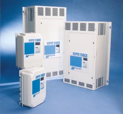
Yaskawa GPD 503 Drives

Installation of Yaskawa GPD 503 Drives:

1. Be certain your input voltage source, motor, and drive name plates are all marked either 230V, 460V, or 575V. Other voltages can be used, but they require additional programming.

2. Mount drive on vertical surface with adequate space for air circulation.

3. Remove front cover, fit conduit to bottom plate, and connect power and ground wires.

Caution: Be certain you connect power to terminals L1, L2, and L3 only, or serious damage will result. Connect motor to T1, T2, and T3 only.


Installation of External Run/Stop Switch and Speed Potentiators:

Important: Complete the Installation and Keypad Operation before attempting external control.

  1. Disconnect power, remove cover, and wait for “CHARGE” light to go out.
  2. Connect a switch to terminals 1 and 11 using two conductor shielded wire. This circuit is 24Vdc, very low current; use a quality rotary or toggle switch (all wire should be 14-18AWG). Connect the shield to terminal 12 on the drive end only.
  3. Install a single conductor “jumper wire” between drive terminals 5 and 11.
  4. Connect a manual speed potentiometer rated 2000-3000 ohms, 1 watt minimum, using three conductor shielded wire, with shield connected at terminal 12. Connect wires to the potentiometer. Trace wire closest to the top and connect to terminal 17. Trace center wire of potentiometer through and connect to terminal 16. The remaining wire will be connected to the trim pot in step 5.
  5. Connect a trim potentiometer rated 2000-3000 ohms, 1 watt minimum, as close to the drive terminals as possible. Viewing the potentiometer from the back, connect a single conductor wire from the left terminal to terminal 15 of the drive. Connect a short jumper wire between the center and left terminals. Connect remaining wire from manual speed pot as shown.
    Check out our other Yaskawa products, including GPD-505 and GPD-506 drives!
    MRO Electric and Supply Company carried new and remanufactured Yaskawa GPD 503 Drives. To place an order or for more information, call 800-691-8511 or email sales@mroelectric.com.

    Yaskawa GPD 503 Drives
    Yaskawa GPD 503 Drives

Human Machine Interface (HMI) Retrofitting

At MRO Electric and Supply, we are experts at retrofitting older HMIs with a new interface that is clean, modernized, and still works with your system.

Take this older Fanuc HMI as an example. The old CRT display has begun to fade out, making its use inefficient and none user-friendly. Old CRT screens are also prone to overheating, and they take up a lot of much needed space.

Fanuc HMI
Fanuc HMI Pre-Retrofit

A new LCD retrofitted screen can give you more accessibility, brighter displays, and user-friendly colors. MRO Electric can quickly update your FANUC Displays and HMIs at a fraction of the cost of replacing your whole HMI. You also don’t have to rewrite your programming, or waste time and resources replacing your whole system.

Fanuc HMI next to LCD Retrofit
Fanuc HMI next to its LCD Retrofit

Below is a fully retrofitted Fanuc HMI with an LCD monitor. This lighter, energy-efficient replacement adds years of life and service to existing legacy equipment, and eliminates potential future downtime. In addition, all of our HMI repairs come standard with a 12 month warranty.

Newly Retrofitted Fanuc HMI

Get in touch with us today to learn more about this cost effective solution for your HMIs. You can request a quote by calling 1-800-691-8511 or by emailing sales@mroelectric.com.

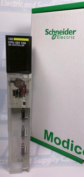
140CPU43412A Error Codes and Hot Standby

Our previous blog post on the 140CPU43412A describes the 140CPU43412A Configuration and Setup. 

140CPU43412A Hot Standby

You cannot create a Quantum Hot Standby configuration running one 140CPU53414A PLC with Unity firmware and one with NxT firmware. When using an NxT configuration in hot standby, both PLCs must have NxT firmware. When using a Unity Quantum hot standby configuration, only specific hot standby controllers can be used. The 140CPU43412A and 140CPU53414A PLCs are not supported in Unity Hot Standby configurations.

140CPU43412A Error Codes

The following are the error codes for the 140CPU43412A:

140CPU43412A Error Codes

For ordering info or for a 140CPU43412A price quote you can call 1-800-691-8511 or email sales@mroelectric.com.

140CPU43412A Firmware Part II

Phase 1 of firmware restoration is described in our previous blog post on the 140CPU43412A firmware.

140CPU43412A Firmware Part II

Restoring a 140CPU43412U (Unity) to 140CPU43412A (Concept):

Phase 2

During the download:

• Do not power OFF the PLC

• Do not power OFF the PC

• Do not disconnect the cable

• Do not shut down OS loader

Any loss of communication during the update procedure can cause severe damage to the CPU or NOE module. Failure to follow these instructions can result in injury or equipment damage.

Reset the PLC

Once the download of the intermediate binary file has completed, the PLC has to be initialized. This task can be performed by one of the two following actions:  Reset the PLC by pushing on the Restart button located on the CPU (for more information, refer to the PLC technical documentation).  Power OFF then ON the PLC. Once the PLC has restarted, go to Phase 3: download the final Concept OS.

Phase 3

Presentation

The final binary file “q5rv135E.bin ” (140CPU34312 in our example) has to be downloaded. For that, follow the same procedure as the one described in the Phase 1.

Checking Version (optional)

If needed, you can check the new CPU version. For that  Open the OS loader tool.  Select the communication protocol.  Click on “Connect.” Then Click on “Properties.”

For ordering info or for a 140CPU43412A price quote you can call 1-800-691-8511 or email sales@mroelectric.com.

140CPU43412A
140CPU43412A FIrmware

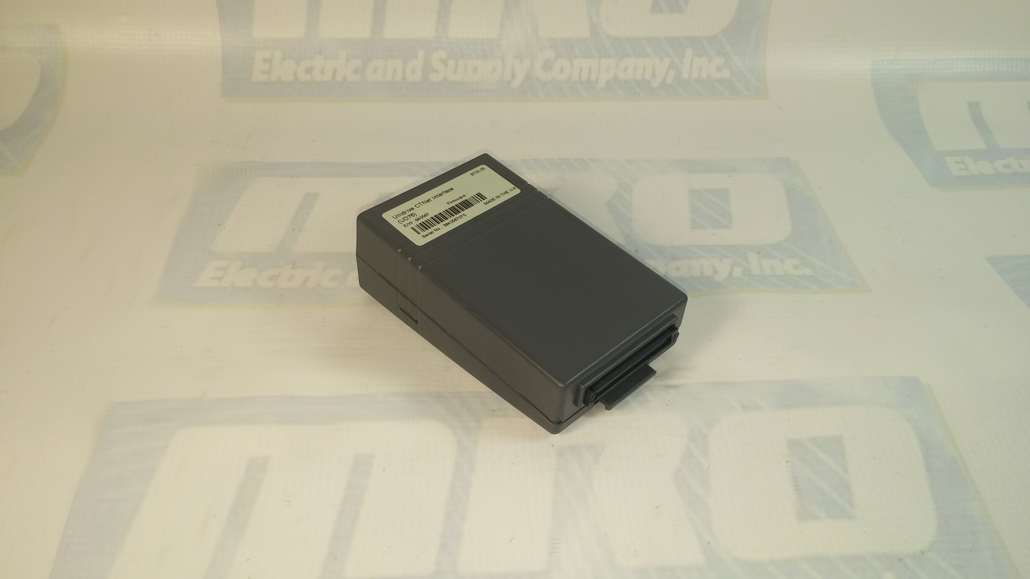
UD75 Configuration and Setup

You can check out our previous blog post  on the UD75 here for more information. Check out the UD75 product page on our website along with all of our other Unidrive options.

UD75 Configuration
  1. Isolate the drive from the mains supply and allow 5 minutes for the DC Bus capacitors to discharge.
  2. Insert Large Option Module as shown below. Ensure that it is correctly inserted. The module will click firmly into place.
  3. To remove the module, pull on the black tab, and the module will disengage from the connector and pull out of the drive.
UD75 Configuration: Cable Screen
The screen of the cable at every node on the network MUST be connected to the screen terminal (pin 3) on the CTNet terminal block. When the screen is stripped back to connect the twisted pair to the CTNet terminals, keep the exposed section of the cable as short as possible. On the CTNet PC Interface Adapter Card, there is no screen terminal. The screen should be cut and taped back to prevent it coming into contact with any other surfaces. The on-board terminal resistor should not be connected.
UD75 Configuration: Network Termination
The network MUST be fitted with terminating resistors AT BOTH ENDS!!! If resistors are not fitted, the network appear to work OK, but the noise immunity of the network will be drastically reduced. The terminating resistor value should match the nominal characteristic impedance value for the cable; in the case of the customized CTNet cable, the terminating resistors used should be nominally 78Ω. PC ISA and PCMCIA cards for interfacing a PC to CTNet are available from CT SSPD.

For price and ordering info you can email sales@mroelectric.com or call 1-800-691-8511. We have these and all the other Control Techniques Unidrive Classic option modules in stock, along with the drives themselves.

UD75 Configuration
UD75 Configuration