In today’s highly automated world, machines and industrial processes are controlled by sophisticated electronic devices that ensure efficiency, precision, and safety. One of the key players in this realm is the Programmable Logic Controller (PLC). PLCs are the unsung heroes behind the automation of countless industries, from manufacturing and agriculture to energy production and beyond. In this comprehensive guide, we will delve deep into the world of PLCs to understand how they work, their applications, components, programming, and their significance in modern industrial automation.
Chapter 1: The Basics of PLCs
1.1 What is a PLC?
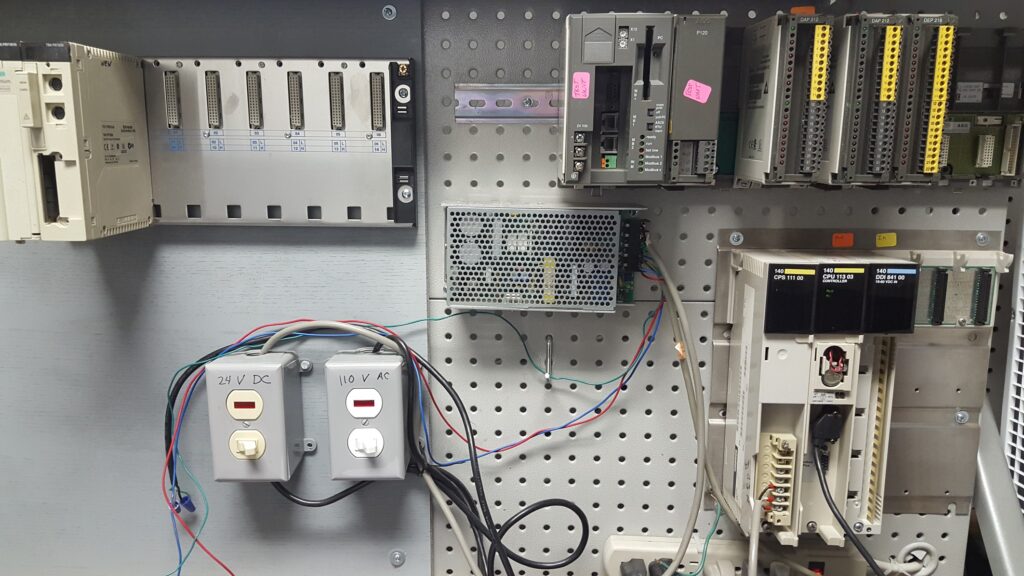
A Programmable Logic Controller (PLC) is a specialized computer designed to control and automate industrial processes and machinery. Unlike general-purpose computers, PLCs are tailored for reliability, ruggedness, and real-time control. They are commonly used in manufacturing plants, chemical processing, power generation, and various other industries.
1.2 Why Use PLCs?
PLCs offer several advantages over traditional relay-based control systems:
- Flexibility: PLCs are highly adaptable and can be reprogrammed to handle different tasks without the need for hardware changes.
- Reliability: PLCs are known for their robustness, with long lifespans and resistance to environmental factors.
- Real-time Control: They provide precise control over processes with minimal delay.
- Diagnostics: PLCs offer extensive diagnostic capabilities, making troubleshooting and maintenance easier.