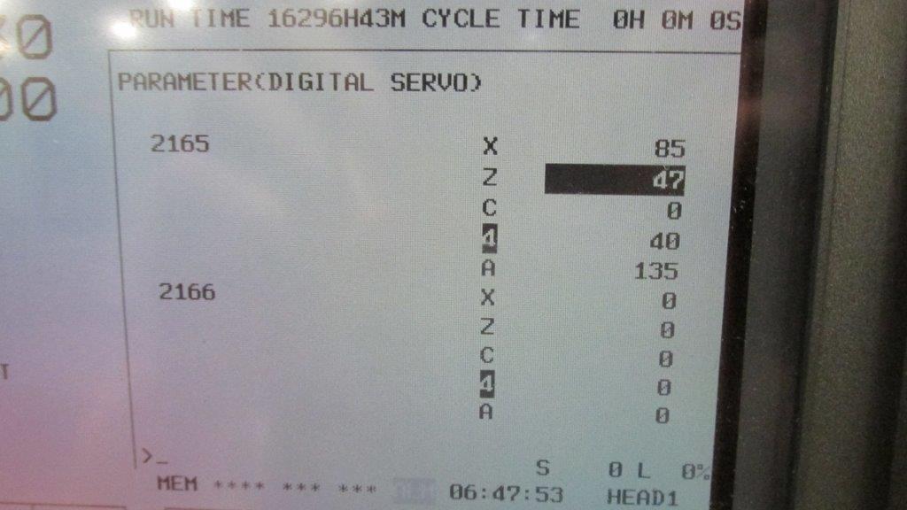
Assigning a 140 NOE Module Ethernet Address Parameter

140NOE77101
140NOE77101

If you have just received the Schneider 140 NOE 771 xx module but have not yet programmed it with an Ethernet configurable extension, you will need to assign an IP address to your module. In this guide you’ll receive information about assigning a 140 NOE Module Ethernet Address Parameter.
Using the BOOTP Lite software utility you can assign IP address parameters. One thing to note, however, is that with the modules 140 NOE 771 01, -11, and NWM 100 00 you can assign the IP address using web pages.

Read More

Upgrading From FANUC C Series Servo Amplifier to α Series

If you experience a system failure due to a Fanuc C series servo amplifier, (A06B-6066-H002, H003 etc.) you may feel like your only option is to replace it with the same exact unit. However Fanuc also offers the α series servo amplifiers which features improvements over the C series. In most cases you can replace your C series servo amplifier with the α series servo amplifier that has the identical final four numbers of the C series model number. The chart below outlines this:

The advantages of replacing your C series amplifier with an α series amplifier are:

  • A built in power supply
  • A second interface, type B, as well as the more conventional type A interface
  • Updated power device, intelligent power module, to reduce power loss and increasing reliability

α series amplifiers are also designed with the same dimensions as the C series so that you can install them into your current system easier.

Go to our website to check out our selection of C series and α series FANUC amplifiers.

A06B-6117-H211 Alarm Code Troubleshooting

 List of A06B-6117-H211 Alarm codes that should help you with troubleshooting. If you do decide you need more help or want to replace your unit, give us a call at 800-691-8511 or email sales@mroelectric.com. You can also visit our product page for the A06b-6117-H211 for more info, or check out all of our FANUC motors and drives.
Alarm Code 1
      (1)Meaning Inverter: internal cooling fan stopped
      (2)Cause and troubleshooting
              (a)Check whether there is any foreign material in the fan.
              (b)Check that the fan connector is attached correctly.
              (c)Replace the fan.
              (d)Replace the SVM.
Alarm Code 2
     (1)Meaning Inverter: control power supply under voltage
     (2)Cause and troubleshooting
              (a)Check the three-phase input voltage of the amplifier (the voltage shall not be lower than 85% of the rated input voltage).
              (b)Check the 24 V power supply voltage output from the PSM (the voltage shall normally not lower than 22.8 V).
             (c)Check the connector and cable (CXA2A/B).
             (d)Replace the SVM.
Alarm Code 5
      (1)Meaning Inverter: DC
link under voltage
      (2)Cause and troubleshooting
              (a) Check that the screws for the DC link connection cable (bar) are tight.
              (b)If a DC link low voltage alarm condition occurs in more than one module, see Subsection 3.1.4, “Alarm code 4” for explanations about how to troubleshoot the power supply module.
              (c)If a DC link low voltage alarm condition occurs in only one SVM, replace that SVM.
Alarm Code 6
     (1)Meaning Inverter: overheat
     (2)Cause and troubleshooting
            (a)Check that the motor is being used at or below its continuous rating.
            (b)Check that the cooling capacity of the cabinet is sufficient (inspect the fans and filters).
            (c)Check that the ambient temperature is not too high.
            (d)Replace the SVM.
Alarm Code F
     (1)Meaning Inverter: cooling
fan stopped of the radiator
     (2)Cause and troubleshooting
          (a)Check whether there is any foreign material in the fan.
          (b)Check that the fan connector is attached correctly.
          (c)Replace the fan.
          (d)Replace the SVM.
Alarm Code P
     (1)Meaning Communication error between amplifier and module
     (2)Cause and troubleshooting
          (a)Check the connector and cable (CXA2A/B).
          (b)Replace the control printed-circuit board.
          (c)Replace the SVM.
Alarm Code 8
     (1)Meaning Inverter: DClink current alarm
     (2)Cause and troubleshooting
           (a)Disconnect the motor power leads from the SVM, and release the SVM from an emergency stop condition.
              <1>If no abnormal DC link current alarm condition has occurred. Go to (b).
             <2>If an abnormal DC link current alarm condition has occurred. Replace the SVM.
          (b)Disconnect the motor power leads from the SVM, and check the insulation between PE and the motor power lead U, V, or W.
                 <1>If the insulation is deteriorated. Go to (c).
                 <2>If the insulation is normal. Replace the SVM.
         (c)Disconnect the motor from its power leads, and check whether the insulation of the motor or power leads is deteriorated.
                <1>If the insulation of the motor is deteriorated. Replace the motor.
                <2>If the insulation of any power lead is deteriorated. Replace the power lead.
Alarm Code 8.9.A.
     (1)Meaning Inverter: IPM alarm
     (2)Cause and troubleshooting
             (a)Disconnect the motor power leads from the SVM, and release the SVM from an emergency stop condition.
                   <1>If no IPM alarm condition has
occurred. Go to (b).
                   <2>If an IPM alarm condition has occurred. Replace the SVM.
            (b)Disconnect the motor power leads from the SVM, and check the insulation between PE and the motor power lead U, V, or W.
                   <1>If the insulation is deteriorated. Go to (c).
                   <2>If the insulation is normal. Replace the SVM.
            (c)Disconnect the motor from its power leads, and check whether the insulation of the motor or power leads is deteriorated.
                   <1>If the insulation of the motor is deteriorated. Replace the motor.
                    <2>If the insulation of any power lead is deteriorated. Replace the power lead.
Alarm Code 8.9.A.
     (1)Meaning Inverter: IPM alarm (OH)
     (2)Cause and troubleshooting
             (a)Check that the heat sink cooling fan is running.
             (b)Check that the motor is being used at or below its continuous rating.
             (c)Check that the cooling capacity of the cabinet is sufficient (inspect the fans and filters).
             (d)Check that the ambient temperature is not too high.
             (e)Replace the SVM.
Alarm Code bcd
       (1)Meaning Abnormal inverter motor current
       (2)Cause and troubleshooting
              (a)Checking the servo parameters Referring to “FANUC AC SERVO MOTOR i series Parameter Manual (B-65270EN),” check whether the following parameters have default values.
Fanuc-15i PRM 1809, 1852, 1853
Fanuc-16i/18i/21i PRM & Power Mate i No.2004, 2040, 2041
For more help or a quote to replace your unit, give us a call at 800-691-8511 or email sales@mroelectric.com.
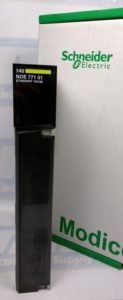
Fanuc A06B-6050-H103 Servo Jumper Settings

When replacing a Fanuc A06B-6050-H103 Servo unit you should check to make sure the replacement servo has the same top board, part number A20B-1000-0560. After this part number there will be a “/” and then something similar to “05A” which denotes the revision of the board. Ideally you would match your original unit with a replacement unit that has the same board, but if that’s not possible then all you would need to do is reconfigure the jumpers on the board. The table below shows how to get this set up so you can get your servo back up and running right away. Search for more FANUC motors/drives on our website.

MRO Electric and Supply maintains a comprehensive stock of new and used FANUC CNC and FANUC Robots parts. If you need a FANUC replacement part, please call 800-691-8511 or email sales@mroelectric.com.
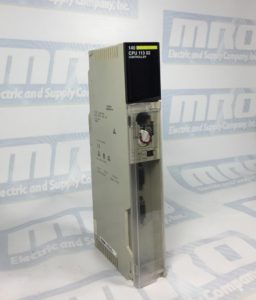
Fanuc Alarm 466 – Z Axis: Motor/Amp Combination

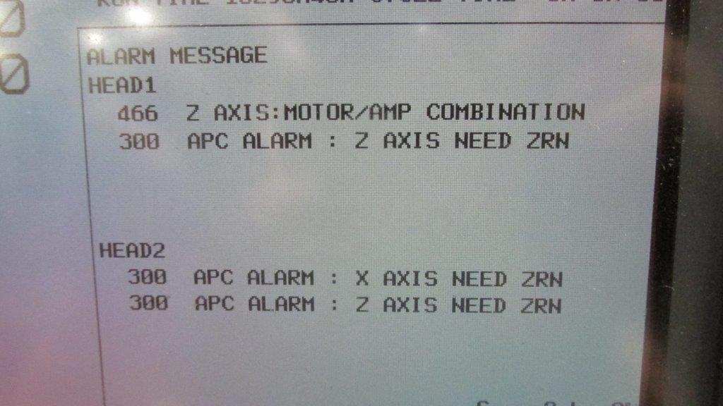
We just shipped out a Fanuc A06B-6096-H207 Servo Amp unit to a customer, and as soon as they installed the amplifier they got a Fanuc Alarm 466 which refers to the Z Axis: Motor/Amp Combination. This is obviously somewhat distressing for a customer to buy a replacement unit and immediately get an alarm when it is installed, but fortunately this is an easy fix.

This Alarm 466 comes from the replacement amplifier having newer servo software than the unit that it is replacing. As Fanuc has made newer units they’ve upgraded the software/hardware within these amplifiers, so you just need to reset a parameter to reboot the configuration and clear the 466 Alarm. The steps are below.

– Put the machine in Emergency Stop
– Go to parameter 2165 on the control
– Set all the values to 0
– Take the machine out of emergency stop

Once these parameters are changed and the machine is rebooted, the alarm will clear and the amplifier will initialize. We also have pictures below to confirm that you know what to look for. For any additional help, call us at 800-691-8511 or email sales@mroelectric.com.
FANUC Alarm 466
FANUC Alarm 466
FANUC Alarm 466
FANUC Alarm 466
MRO Electric stocks a large number of FANUC CNC Products, and provides repair services as well. For more information or to request a quote, please call 800-691-8511 or email sales@mroelectric.com.