Understanding PLCs (Programmable Logic Controllers): A Comprehensive Guide

In today’s highly automated world, machines and industrial processes are controlled by sophisticated electronic devices that ensure efficiency, precision, and safety. One of the key players in this realm is the Programmable Logic Controller (PLC). PLCs are the unsung heroes behind the automation of countless industries, from manufacturing and agriculture to energy production and beyond. In this comprehensive guide, we will delve deep into the world of PLCs to understand how they work, their applications, components, programming, and their significance in modern industrial automation.

Chapter 1: The Basics of PLCs

1.1 What is a PLC?

A Programmable Logic Controller (PLC) is a specialized computer designed to control and automate industrial processes and machinery. Unlike general-purpose computers, PLCs are tailored for reliability, ruggedness, and real-time control. They are commonly used in manufacturing plants, chemical processing, power generation, and various other industries.

1.2 Why Use PLCs?

PLCs offer several advantages over traditional relay-based control systems:

  • Flexibility: PLCs are highly adaptable and can be reprogrammed to handle different tasks without the need for hardware changes.
  • Reliability: PLCs are known for their robustness, with long lifespans and resistance to environmental factors.
  • Real-time Control: They provide precise control over processes with minimal delay.
  • Diagnostics: PLCs offer extensive diagnostic capabilities, making troubleshooting and maintenance easier.
Read More

Common UNI1405 Fault Codes

Below is a table of common Unidrive faults found within the Control Techniques Unidrive series, more specifically, the UNI1405. MRO Electric offers core credit on exchanges for new and refurbished units, and have a wide selection of option cards such as the UD51, UD73, and UD77. We also repair Unidrives in-house. Contact us if you are interested in finding a new machine so we can keep your downtime to a minimum!

HF81Software Error (odd address word)
HF82Large option module removed
HF83Power Board Code Failure
HF84Current Offset Trim Failure
HF85A to D failure (ES-CC step)
HF86Interrupt Watchdog failure
HF87Internal ROM check error
HF88Watchdog Failure
HF89Unused Interrupts (nmi as source)
HF90Stack Overflow
HF91Stack Underflow
HF92Software Error (undefined op code)
HF93Software Error (protection fault)
HF94Software Error (odd address word)
HF95Software Error (odd address inst.)
HF96Software Error (illegal ext bus)
HF97Level 1 Noise
HF98Interrupt Crash
HF99Level 1 Crash
Micromaster 420

Siemens Micromaster 420 Faults and Alarms

Siemens Micromaster 420: Troubleshooting Faults and Alarms

A blog we posted earlier this week about the Micromaster 420 troubleshooting referenced the Faults and Alarms list for the Micromaster series, so we decided that it would make sense to make the list of Micromaster 420 Faults and Alarms directly available. This is from the corresponding manual for the Micromaster 420 series, but it is buried within the manual which most people most likely don’t even have. Hopefully, this helps with your troubleshooting of Siemens drive fault codes and alarms.

Be sure to also check out our list of Siemens Micromaster 440 fault codes and our article touching on Siemens Simodrive E/R Module Fault Troubleshooting, along with other Siemens series coverage.

If you’re looking to purchase a Siemens Micromaster drive, view our 420 Micromaster Drives in stock. For more information or to request a quote, please call 800-691-8511 or email sales@mroelectric.com. We also provide pre-priced Micromaster 420 Repairs.

Read More

Siemens Sinamics CU320 Modules: Beyond the User Manual

About Sinamics S120 CU320 Modules

There are two Sinamics S120 CU320 Modules. There is the CU320-2 DP, which is the 6SL3040-1MA00-0AA0, and the CU320-2 PN, which is the 6SL3040-1MA01-0AA0.

These multi-drive Control Units increase axis count and functionality. They have an Ethernet port, as well as more I/O and controller to controller communication. Each unit can manage up to 6 servo or vector axes in a high performance system. For standard systems, up to 12 V/Hz axes can be controlled from one CU320-2 unit. These Control Units significantly reduce system costs, as they increase functionality for positioning, safety integration, and drive control allowing all these functions to be controlled by one unit versus several.

Siemens CU320 control units also provide additional flexibility with a high number of programming options and digital inputs. With up to 12 binary inputs, the modules’ high I/O count add ease of use. The additional Ethernet port expands programming options as well. Overall, the CU320-2 control units allow for simple yet flexible performance with minimal cost and space requirements.

If you want to learn more about these high-performance drives, check out our blog on Sinamics s120 fault codes.

CU320-2 DP Module

CU320-2 DP

The CU320-2 DP is a Sinamics Control Unit with a Profibus interface. It is a central Control Module in which the closed-loop and open-loop functions are implemented for one or more Line Modules and/or Motor Modules. It can be used with firmware version 4.3 or greater. It has 12 digital inputs, 8 digital inputs/outputs, 4 DRIVE-CLiQ interfaces, a Profibus and Ethernet interface, a serial interface (RS232), an option slot, and 3 measuring sockets.

MRO Electric stocks new and refurbished CU320-2 DP Control Units, which is part number 6SL3040-1MA00-0AA0. If you would like a replacement module, please call 800-691-8511 or email sales@mroelectric.com.


CU320-2 PN Module

CU320-2 PN

The CU320-2 PN is a Sinamics S120 Control Unit without a Profibus interface. It has the same interfaces as described above, however without the Profibus port. It is also a central control unit with closed-loop and open-loop functions that can be implemented for one or more Line or Motor modules.

MRO Electric stocks new and refurbished CU320-2 PN Control Units, which is part number 6SL3040-1MA01-0AA0. If you would like a replacement module, please call 800-691-8511 or email sales@mroelectric.com.

Sinamics S120

Sinamics S120 Fault Codes and Alarms, Part I

It is important to understand the differences between faults and alarms on Sinamics S120 Drives by Siemens. We have included a list of common faults and alarm codes for S120 drives, what they mean, likely causes and how to fix the fault or alarm. For more Sinamics S120 faults and alarms, check out Part II and Part III of the series that we will be posting shortly. Be sure to check out our website to browse all of our Siemens products.

Understanding Faults 

What happens when a fault occurs?

  • The appropriate fault reaction is initiated
  •  Status signal ZSW1.3 is set.
  • The fault is entered in the fault buffer.

How are faults eliminated?

  • Remove the original cause of the fault
  • Acknowledge the fault

Understanding Alarms

What happens when an alarm occurs?

  • Status signal ZSW1.7 is set.
  • Alarms are “Self Acknowledging” meaning they are reset when the cause of the alarm has been eliminated.

List of Sinamics S120 Faults and Alarms

F01000:  Internal software error

Message Value: Module: %1, Line: %2
Drive Object: All Objects
ReactionOFF2
AcknowledgePOWER ON
Cause: An internal software error has occurred. Fault value (r0949, interpret hexadecimal)
Remedy

  • Evaluate fault buffer
  • Carry out a POWER ON (power on/off) for all components.
  • If required, check the data on the non-volatile memory (memory card).
  • Upgrade firmware to a later version.
  • Replace the control unit or contact MRO Electric.

F01001:  Floating Point Exception

Message Value: %1
Drive Object: All objects
Reaction: OFF2
AcknowledgePOWER ON
Cause: An exception occurred during an operation with the FloatingPoint data type. The error may be caused by the basic system or the OA application (e.g. FBLOCKS, DCC).
Remedy:

  • Carry out a POWER ON (power on/off) for all components.
  • Check configuration and signals of the blocks in FBLOCKS.
  • Check configuration and signals of DCC charts.
  • Upgrade firmware to a later version.
  • Contact Service Hotline.

F01002:  Internal software error

Message Value: %1
Drive Object: All objects
Reaction: OFF2
Acknowledge: IMMEDIATELY
Cause: An internal software error has occurred
Remedy: 

  • Carry out a POWER ON (power on/off) for all components.
  • Upgrade firmware to a later version.
  • Contact Service Hotline.

F01003:  Acknowledgement delay when accessing the memory

Message Value: %1
Drive Object: All objects
Reaction: OFF2
Acknowledge: IMMEDIATELY
Cause: A memory area was accessed that does not return a “READY”.
Remedy: 

  • Carry out a POWER ON (power on/off) for all components.
  • Contact Service Hotline

N01004 (F, A):  Internal software error

Message Value: %1
Drive Object: All objects
Reaction: NONE
Acknowledge: NONE
Cause: An internal software error has occurred. 
Remedy:  Read out diagnostics parameter (r9999).
Reaction upon F: OFF2
Acknowl. upon F: POWER ON
Reaction upon A:  NONE
Acknowl. upon A: NONE

F01005:  Firmware  download for DRIVE-CLiQ component unsuccessful

Message Value: Component number: %1, fault cause: %2
Drive Object: All objects
Reaction: NONE
Acknowledge: IMMEDIATELY
Cause: It was not possible to download the firmware to a DRIVE-CLiQ component
Remedy:

  • Check the selected component number
  • Check the DRIVE-CLiQ connection
  • Save suitable firmware file for download in “/siemens/sinamics/code/sac/”
  • Use a component with a suitable hardware version
  • After POWER ON has been carried out again for the DRIVE-CLiQ component,                               download the firmware again. Depending on p7826, the firmware will be                                       automatically downloaded.

A01006: Firmware update for DRIVE-CLiQ component required

Message Value: Component number: %1
Drive Object: All objects
Reaction: NONE
Acknowledge: NONE
Cause: The firmware of a DRIVE-CLiQ component must be updated as there is no suitable firmware or firmware version in the component for operation with the Control Unit.
Alarm value (r2124, interpret decimal): Component number of the DRIVE-CLiQ component
Remedy: 

  • Firmware update using the commissioning software:
    • The firmware version of all of the components on the “Version overview” page can be read in the Project Navigator
      under “Configuration” of the associated drive unit and an appropriate firmware update can be carried out.
  • Firmware update via parameter:
    • Take the component number from the alarm value and enter into p7828.
    • Start the firmware download with p7829 = 1.

A01007: POWER ON for DRIVE-CLiQ component required

Message Value: Component number: %1
Drive Object: All objects
Reaction: NONE
Acknowledge: NONE
Cause: A DRIVE-CLiQ component must be powered up again (POWER ON) (e.g. due to a firmware update). 

Alarm value (r2124, interpret decimal): Component number of the DRIVE-CLiQ component. If the component number is 1, a POWER ON of the Control Unit is required. 
Remedy: 

  • Switch off the power supply of the specified DRIVE-CLiQ component and switch it                   on again.
  • For SINUMERIK, auto commissioning is prevented. In this case, a POWER ON is                           required for all components and the auto commissioning must be restarted.

A01009 (N):   CU: Control module overtemperature

Message Value: –
Drive Object: All objects
Reaction: NONE
Acknowledge: NONE
Cause: The temperature (r0037[0]) of the control module (Control Unit) has exceeded the specified limit value.
Remedy:

  • Check the air intake for the Control Unit.
  • Check the Control Unit fan.

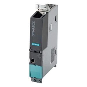
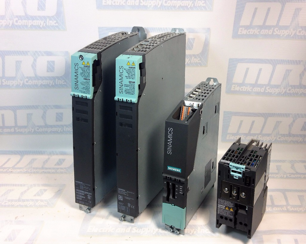
MRO Electric and Supply carries new and used Sinamics modules. For more information or to request a quote, call 800-691-8511 or email sales@mroelectric.com.

Dealing with Sinamics S120 Fault Codes?

Fault codes on your Sinamics S120 can be a major setback. MRO Electric provides the expertise and parts you need to diagnose and resolve issues swiftly, ensuring your drive system runs smoothly without extended downtime.

Elevate Your Production and Learn More About KUKA Robot Arms

KUKA Robotics

Updated August 2019: You can purchase KUKA products, including KUKA arms, directly from our website.

MRO Electric and Supply distributes a variety of new and refurbished KUKA Robot arms.

We repaint and rebuild all of our refurbished KUKA arms, as well as purge and replace the grease according to the manufacturer’s specifications.

KUKA Robot Arm Models

We supply KUKA arms and wrists from a number of robots. We have included some popular KUKA robot models in our inventory below:

  • KR30
  • KR60
  • KR90
  • KR150
  • KR180
  • KR360
  • KR500
  • Any Many More!

About KUKA Robotic Arms

Most KUKA robotic arms are made up of 4-6 joints, and can be used for many different applications such as welding, material handling, material removal, and more. Because KUKA arms are so large, they are typically used to lift heavy payloads and are sometimes run by hydraulic and pneumatic methods. Most KUKA robot arms are made from aluminum and built from the base up, ending with the wrist and whichever end effect is needed to help the arm perform its given application.

KUKA was one of the first companies to use aluminum in robot arm design, which makes KUKA arm manipulators one of the fastest and lightest on the market. They also introduced a horizontal balancing spring on axis 2 before the other robot manufacturers, a design that has now been widely adopted.

Even if you are new to programming, you can explore different intuitive programming options to find out what will work best for you. KUKA robotic arms can be programmed in multiple ways including using KUKA’s own robot language, through hand guiding, a handheld probe, graphical offline programming and more.

MRO Electric and Supply has a warehouse full of many types of KUKA arms and wrists. Give us a call today if you need a replacement and we can usually ship you one same-day! You can also email sales@mroelectric.com for a quote.

Testing Your Fanuc Servo Motor

Here are some basic principles for troubleshooting a FANUC motor circuits with meter or megohm meter. This procedure will show you how to test for shorts in windings, cables, or opens. Before starting to test, make sure to turn all all the power sources to the machine and then disconnect the 3-phase motor lines from the drive end. Visually confirm that there are no problems with the cable and then begin testing.

Testing for a short to ground:

Using an Ohm meter:

  • Disconnect all power and amplifiers from machine. Check all three wires at T1, T2, and T3 (all three phases) to the ground wire. The readings for this should be infinite, and if it is zero or reads any continuity then there is a problem with the motor or the cable. For this disconnect the cable and check each separately. Be sure to make sure leads on both ends are not touching anything, including the other leads. Most servo motor shorts can be ready with a regular quality  meter going to at least 10 megaohms.

Using a Megohm meter:

  • Disconnect all power from machine. Check all three wires at T1, T2, and T3 (all three phases) to the ground wire. Reading should be between 600-2000 Megohms. Most shorts will be below 20 Megohms. Be careful not to touch the leads or the wires to anything when taking the reading because it can give a false reading. There should be about 1000 Ohms of resistance for each volt of incoming power, but this is not a standard rule. If it is 230meg to 600meg there may be deterioration in the cable.

Testing for Open or Short in the windings:

Using an Ohm meter:

  • Disconnect all power from the machine. Put meter on ohms and test T1 to T2, T2 to T3, and T1 to T3. The range should be between 0.3 and 2.0 ohms, with most being at about 0.8 ohms. If it is zero there is a short between the two phases. If it is an open the reading will be infinite or well above 2,000 ohms.

Cable and plug notes:

  • Often times the connector on the cable to the motor will get coolant in it. You can dry it out an retest, if it is still bad the inserts will get burn marks in them and cause a slight short, so they need to be replaced. If it is a DC motor, check the brushes. There should be 3-4 round caps to remove around the motor. Under these there is a spring with a square block (brush). Check to see how much is left, they may need to be replaced.


MRO Electric has a large stock of FANUC motors available. If you would like a replacement or spare, or if you have any questions, please call 800-691-8511 or email sales@mroelectric.com. To check out other posts, please visit our blog page.