140CPU43412A Configuration and Setup

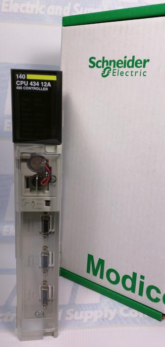
You can check out our previous blog post on the 140CPU43412A manual and configuration here for additional setup info.

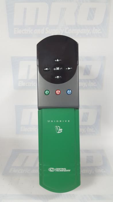
Front Panel Topology
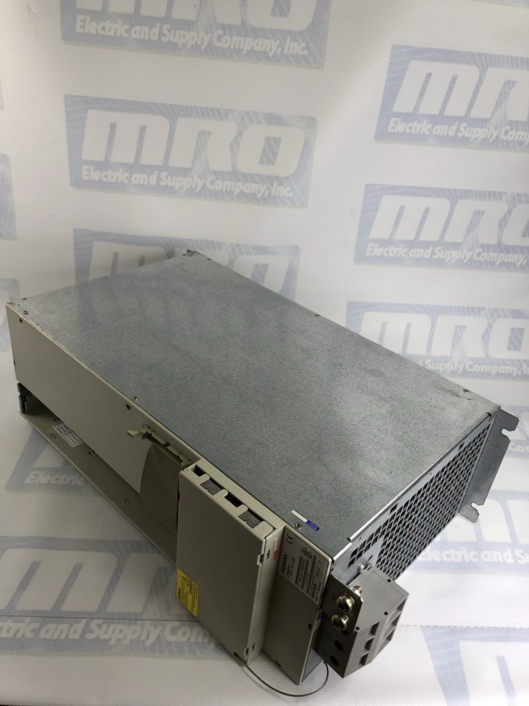
There are two switches (a three-position slide switch and a three-position key switch) located on the front of the 140CPU43412A configuration. The module has a single slide switch that is used to select the comm parameter settings for the Modbus (RS-232) ports.
Rear Panel Topology

The address switch, which is comprised of two rotary switches, is located on the rear panel of the Quantum CPUs. The address switch is used for setting Modbus Plus node and Modbus port addresses. SW1 (the top switch) sets the upper digit (tens) of the address, SW2 (the bottom switch) sets the lower digit (ones) of the address. The illustration below shows the correct setting for an example address of 11.

Option Module Interface Support

The 140CPU43412A firmware supports up to six network modules (i.e., Modbus Plus, Ethernet, and Multi-Axis Motion option modules) using the option module interface technique. However, only two Modbus Plus modules can have full functionality, including Quantum DIO support.

For ordering info or for the 140CPU43412A price you can call 1-800-691-8511 or email sales@mroelectric.com.

140CPU43412A
140CPU43412A

Updated on March 5, 2020 by Brian Hughes

UNI1405

UNI1405 Configuration and Setup

You can check out our previous blog post on the UNI1405 parameters and manual here with additional setup info. Check out our entire collection of Unidrives on our website.

With the UNI1405 configuration, the volts / frequency ratio must be kept constant to ensure rated torque is available from the motor over the frequency range. At low frequencies (from 0 Hz to ½ x Pr 5.06) the voltage is increased from this characteristic by a level governed by either the voltage boost parameter or the motor parameters (found during the stator resistance test) depending on whether the drive is in fixed boost or open loop vector mode as shown aside.

UNI1405 Motor Rated Power Factor

The power factor is found by the UNI1405 4kw during the autotune procedure. It is used in the open loop vector algorithm and to set the current limit levels for the torque producing (active) current.

Emerson UNI1405 4kw Motor Rated Speed

The motor rated speed parameter should be set to the synchronous speed of the motor minus the slip speed. This is often displayed on the motor nameplate. I.e. For a typical 18.5 kW, 50 Hz, 4 pole motor the motor rated speed is 1465 rpm. The synchronous speed for a 4 pole motor is 1500 rpm therefore the slip speed is 35 rpm Synchronous speeds for different numbers of poles are as follows:
2 pole = 3,000 rpm
4 pole = 1,500 rpm
6 pole = 1,000 rpm
8 pole = 750 rpm
The accuracy of this parameter is very important as it directly affects the torque produced at the shaft. Often the value given on the motor nameplate is not
100% accurate which can lead to a loss of torque.
For ordering info or a UNI1405 price you can call 1-800-691-8511 or email sales@mroelectric.com.
UNI1405 Configuration

Updated on March 5, 2020 by Brian Hughes

6SN1123-1AA00-0EA1 Configuration and Setup

The steps for 1p 6SN1123-1AA00-0EA1 Manual Configuration and Setup are below as a follow up to our previous entry here.
 
Start-up Possibilities for 1p 6SN1123-1AA00-0EA1 Configuration
using
- operator control and display elements (refer to Section 1.3)
- RS232C interface with an IBM AT–compatible computer and start–up soft-
ware
 
Re-initialize Drive Converter (if required)
If an already initialized drive–converter is to be re–initialized, then proceed as
follows:
- if required, back–up the setting data (parameters)
- remove write protection: Set P–051 to 4H
- start initialization: Set P–097 to 0H
- overwrite the parameters in the drive–machine data memory: Set P–052 to 1H, and wait until P–052 resets itself to 0H.
- power–on reset:
Power–down the unit and power–up approximately 2 s after the display has disappeared:
P–095 must then appear in the display.
- initialize
 
Firmware Replacement (if required)
The firmware can be replaced using the user–prompted start–up software for
main spindle– and induction motor modules, from version V2.00.
 
Firmware release
before FW 3.00 -> 6SN1121–0BA1_–0AA0
from FW3.00 -> 6SN1121–0BA11–0AA1
 
Procedure:
- back–up setting data (parameters)
- replace the firmware using the start–up program
- initialize with the pulses and controller inhibited
- re–load the backed–up settings
- back–up the setting data in the drive–machine data memory
 
Start-up of series machines, module replacement, component replacement
The drive converter setting data (parameters) can be saved on floppy disk using
the start–up software. Proceed as follows to start–up additional drive converters
(start–up of series machines):
1.Initialize with the pulses and controllers inhibited:
Enter P–095 power module code number
– Motor code number and motor encoder pulse number are saved on the floppy disk, and therefore do not have to be entered.
– Start initialization.
2. Load and save the setting data from the floppy disk.
 
For more info or a 1p 6SN1123-1AA00-0EA1 price you can email sales@mroelectric.com or call 1-800-691-8511.

Updated on March 5, 2020 by Brian Hughes

140CPU53414B Configuration and Setup

During the 140CPU53414B firmware configuration, there are two switches (a three-position slide switch and a three-position key switch) and one connector (Modbus RS-232) located on the front of the CPU.

The slide switch is used to select the comm parameter settings for the 140CPU53414B configuration of Modbus (RS-232) ports. Three options are available, ASCII, RTU, and mem.

Read More

Updated on March 5, 2020 by Brian Hughes

UNI2403 Configuration and Setup

The UNI2403 and UNI2403-r configuration process is a relatively simple setup process that should be able to get you back up and running with minimal downtime.

With some simple UNI2403 11kw configuration the drive can be used as an AC Regenerative Unit, also known as a Regen Drive. In the case of a drive operating in Regen mode, the IGBT bridge is used as a sinusoidal rectifier, which converts the AC supply to a controlled DC voltage. This DC voltage can then be used to supply one or more Unidrives which control motors, commonly known as motoring drives.

A regen drive produces PWM output voltage which has a sinusoidal fundamental at an amplitude and phase which are almost the same as those of the AC supply voltage. The difference between the drive PWM line voltage and the supply voltage occurs across the Regen drive’s inductors.

There are a number of possible options available when designing a Unidrive Regen system depending on the user requirements and the nature of the AC supply. Non standard systems can be created where favourable supply conditions exist, allowing cost and space savings to be achieved by reducing the number of components.

A Unidrive can be used as a sinusoidal input current power unit to supply one or more Unidrives via their DC buses. When this mode is selected as the drive type, menu 15 appears. This menu is used to set up the Unidrive. At the same time, menu 0 defaults to showing Pr 15.01 to Pr 15.13 as Pr0.11 to Pr 0.28.

You can check out our previous blog post on the UNI2403 manual and UNI2403-r manual here with additional setup info. To get a UNI2403 price quote or for ordering info you can call 1-800-691-8511 or email sales@mroelectric.com.

Updated on March 5, 2020 by Brian Hughes