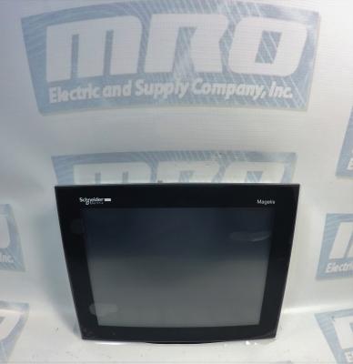
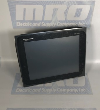
You cannot create a Quantum Hot Standby configuration running one 140CPU53414A PLC with Unity firmware and one with NxT firmware. When using an NxT configuration in hot standby, both PLCs must have NxT firmware. When using a Unity Quantum hot standby configuration, only specific hot standby controllers can be used. The 140CPU43412A and 140CPU53414A PLCs are not supported in Unity Hot Standby configurations.
140CPU43412A Error Codes
The following are the error codes for the 140CPU43412A:
Any loss of communication during the update procedure can cause severe damage to the CPU or NOE module. Failure to follow these instructions can result in injury or equipment damage.
Reset the PLC
Once the download of the intermediate binary file has completed, the PLC has to be initialized. This task can be performed by one of the two following actions: Reset the PLC by pushing on the Restart button located on the CPU (for more information, refer to the PLC technical documentation). Power OFF then ON the PLC. Once the PLC has restarted, go to Phase 3: download the final Concept OS.
Phase 3
Presentation
The final binary file “q5rv135E.bin ” (140CPU34312 in our example) has to be downloaded. For that, follow the same procedure as the one described in the Phase 1.
Checking Version (optional)
If needed, you can check the new CPU version. For that Open the OS loader tool. Select the communication protocol. Click on “Connect.” Then Click on “Properties.”
For ordering info or for a 140CPU43412A price quote you can call 1-800-691-8511 or email sales@mroelectric.com.
Phase 1 – Restore the PLC to Concept with an intermediate OS.
Phase 2 – Power OFF then ON the PLC.
Phase 3 – Restore the Operating System with the appropriate file.
These phases are mandatory and cannot be by-passed.
Phase 1:
Launching the OS Loader
The OS loader (provided with Unity) allows the user to download the Operating System to the PLC. To open it click on Start/Program/SchneiderElectric/Unity-PRO/OS loader.
Select the Communication Protocol
From the main screen of the OS loader, click on the “Next” button. To download the Operating System into the PLC, select the right communication protocol (in accordance with established physical link) and click on the “Next” button.
Select the Target Device
On the Device Type field, select Processor and the other needed parameters (Modbus address….). Then connect to the selected PLC (Node).
Select the Download Function
From the screen described above press the “Next” button. A new screen is proposed: select “Download OS to device”.
Select the File to be Downloaded
Click on the “Browse…” button in order to select the file to download into the PLC. In this example we will restore the OS from 140CPU43412U to 140CPU43412A firmware. For that select the following folders: Quantum\Processor_modules\Unity_to_Concept. To restore the OS from Unity to Concept, two binary files can be selected: Unity_to_Concept_43412A.bin (allows to “format” the processor to Concept) q5rv135E.bin is the OS that will finally be downloaded in the processor. In our example we have to “format” the processor (remember, we still are in the Phase 1) then select and Validate “Unity_to_Concept_43412A.bin”. Once done click on the “Next” button.
Download the Intermediate OS
Once the previous screen is validated a warning is displayed: Click the “Okay” button. Two screens that give information regarding the file, the processor and the download are now displayed. Note: If the system detects a discrepancy on the hardware or on the OS version, the download will not be possible. This is indicated by a red cross and the “Next” button becomes unavailable. Solve this issue and continue. When the hardware – OS are compatible, click on the “Download” button to launch the download of the intermediate OS file.
You can check out our previous blog post on the UD75 here for more information. Check out the UD75 product page on our website along with all of our other Unidrive options.
UD75 Configuration
Isolate the drive from the mains supply and allow 5 minutes for the DC Bus capacitors to discharge.
Insert Large Option Module as shown below. Ensure that it is correctly inserted. The module will click firmly into place.
To remove the module, pull on the black tab, and the module will disengage from the connector and pull out of the drive.
UD75 Configuration: Cable Screen
The screen of the cable at every node on the network MUST be connected to the screen terminal (pin 3) on the CTNet terminal block. When the screen is stripped back to connect the twisted pair to the CTNet terminals, keep the exposed section of the cable as short as possible. On the CTNet PC Interface Adapter Card, there is no screen terminal. The screen should be cut and taped back to prevent it coming into contact with any other surfaces. The on-board terminal resistor should not be connected.
UD75 Configuration: Network Termination
The network MUST be fitted with terminating resistors AT BOTH ENDS!!! If resistors are not fitted, the network appear to work OK, but the noise immunity of the network will be drastically reduced. The terminating resistor value should match the nominal characteristic impedance value for the cable; in the case of the customized CTNet cable, the terminating resistors used should be nominally 78Ω. PC ISA and PCMCIA cards for interfacing a PC to CTNet are available from CT SSPD.
For price and ordering info you can email sales@mroelectric.com or call 1-800-691-8511. We have these and all the other Control Techniques Unidrive Classic option modules in stock, along with the drives themselves.
You can check out our previous blog post on the 6FC5357-0BB35-0AA0 here for more information. Check out our websites to see all of our Siemens products.
The 6FC5357-0BB35-0AA0 configuration features a modular design comprising line filter, commutating reactor, line supply infeed module, drive modules as well as, when required: monitoring, pulsed resistor and capacitor module(s). Satisfactory operation is ensured only in conjunction with the components that are described in the 6FC5357-0BB35-0AA0 Configuration Manual or published in the Catalog NC60 (Internet Mall) and with adherence to the required boundary/application conditions. Modules can also be arranged in several tiers one above the other or next to one another.
The housings of the 6FC5357-0BB35-0AA0 converter system modules are enclosed and EMC–compatible as specified in EN 60529 (IEC 60529). The electrical system is designed to comply with EN 50178 (VDE 0160) and EN 60204, and an EC declaration of conformity is available. The connections in the module group, motor cables, encoder lines and bus lines must be made using preassembled MOTION–CONNECT lines.
Due to the limited conductivity of the DC link busbars of the modules with module width 150 mm, the DC link power PZK of these modules must not exceed 55 kW. Larger DC link busbars must be used if this restriction cannot be complied with. The DC link power PZK of the subsequent modules is calculated according to the engineering rule specified in the manual. The larger DC link busbars can be ordered as a set. The set includes reinforced DC link busbars for module widths 50 mm, 100 mm and 150 mm. The standard DC link brackets between the modules may not be changed, even when strengthened DC link busbars are used.
Since capacitance in the motor cable causes loading on the output of the UNI3405 Drive, ensure the cable length does not exceed 660 ft. (400 volts) or 410 ft. (480 volts).
Cable lengths in excess of the specified values may be used in the UNI3405 configuration only when special techniques are adopted; refer to the supplier of the Drive.
The maximum cable length for the Unidrive UNI3405 configuration is reduced from that shown above under the following conditions:
PWM switching frequency exceeding 3kHz in model sizes 3 and 4 — The maximum cable length is reduced in proportion to the increase in PWM switching frequency, eg. at 9kHz, the maximum length is 1/3 of that shown.
High-capacitance cables – Most cables have an insulating jacket between the cores and the armour or shield; these cables have a low capacitance and are recommended. Cables that do not have an insulating jacket tend to have high capacitance; if a cable of this type is used, the maximum cable length is half that quoted in the table.
The Drive has two forms of thermal protection for the power output stage (IGBT bridge), as follows:
A thermistor mounted on the heatsink monitors the heatsink temperature. If this exceeds 95 °C (203 °F), the thermistor will cause the Drive to trip. The display will indicate Oh2
Intelligent thermal modelling estimates (by calculation) the junction temperature of the IGBTs. There are two temperature thresholds which cause the following to occur:
If the first threshold is reached, the PWM switching frequency is halved in order to reduce dissipation in the IGBTs. (When the frequency is halved, the value of parameter 0.41 PWM switching frequency remains at the value set by the user; if the frequency is 3kHz or 4.5kHz, no halving occurs). Then at one second intervals, the Drive will attempt to restore the original PWM switching frequency. This will be successful if the estimated temperature has reduced sufficiently.
If the estimated temperature has continued to rise and reaches a second threshold, the Drive will trip. The display will indicate Oh1.
You can view our previous blog post on the Siemens 6SN1145-1BA01-0BA1 manual here for more information.
Drive Line-Up
The Siemens 1P 6SN1145-1BA01-0BA1 configuration is modular, comprising line filter, commutating reactor, line supply infeed module, drive modules as well as, when required: monitoring, pulsed resistor and capacitor module(s). Satisfactory operation is ensured only in conjunction with the components that are described in the Configuration Manual or published in the Catalog NC60 (Internet Mall) and with adherence to the required boundary/application conditions. In order to avoid contamination, the modules should be installed in a control cabinet with degree of protection IP 54. Modules can also be arranged in several tiers one above the other or next to one another.
Due to the limited conductivity of the DC link busbars of the modules with module width 150 mm, the DC link power PZK of the Siemens 6SN1145-1BA01-0BA1 configuration must not exceed 55 kW. Larger DC link busbars must be used if this restriction cannot be complied with. The DC link power PZK of the subsequent modules is calculated according to the engineering rule specified in Chapter 1.3 of the manual. The larger DC link busbars can be ordered as a set with Order No. [MLFB] 1P 6SN1161–1AA02–6AA0. The set includes reinforced DC link busbars for module widths 50 mm, 100 mm and 150 mm. The standard DC link brackets between the modules may not be changed, even when strengthened DC link busbars are used.
For a 6SN1161–1AA02–6AA0 price quote and ordering info you can email sales@mroelectric.com or call 1-800-691-8511.