6SN1123-1AA00-0CA2

Siemens 6SN1123-1AA00-0CA2: Beyond the User Manual

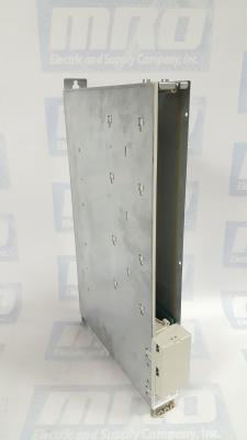
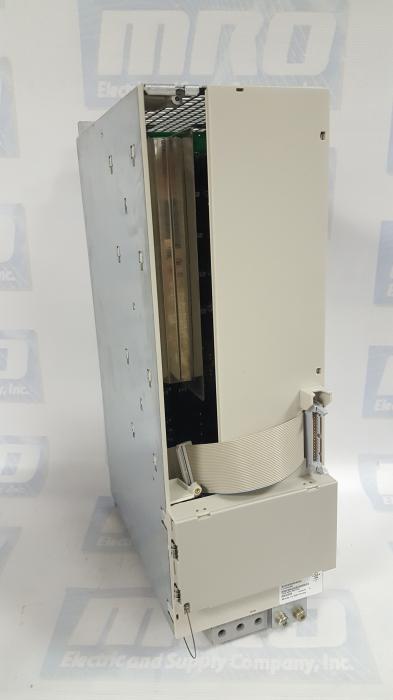
The Siemens 6SN1123-1AA00-0CA2 is a Simodrive 611, 1 Axis Power Module. With the control module, the 6SN1123-1AA00-0CA2 forms the drive module for feed or main spindle applications. The module provides power to the control boards as well as the connected motors. It can be used to operate a variety of Siemens and 3rd party motors. This module is graded according to a certain rating and can be supplied with three different cooling techniques. The module is equipped with overload protection. When this is dimensioned properly,  it prevents both the cables and motors from being overloaded. the power module has two operating modes – one for Feed drives and another for Main spindle drives.

The 6SN1123-1AA00-0CA2 can be used for a variety of solutions due to its modular and space saving attributes. The module’s output limits can be modified by the control module in use. The drive modules can be operated from both an unregulated and regulated supply modules belonging to the Simodrive 611 drive system. The power module draws its supply required to control the motors from the DC link.

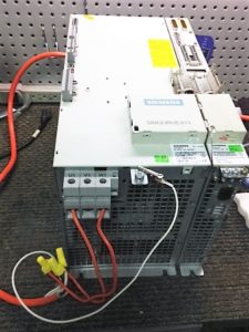
Then installing a control board into the 6SN1123-1AA00-0CA2, make sure the following is observed:

  1. Ensure that the power module is in a no-voltage condition.
  2. Check that the memory module is inserted and locked into place in the control board.
  3. Insert the control board into the power module.
  4. Tighten the screws retaining the board (2 on front panel).
  5. Connect the front panel of the board corresponding with its applicable connection diagram. The mating connectors must be inserted at the appropriate interface.
MRO Electric stocks both new and refurbished 6SN1123-1AA00-0CA2 Power Modules. For more information or to request a quote, please call 800-691-6511 or email sales@mroelectric.com.
6SN1123-1AA00-0CA2
6SN1123-1AA00-0CA2
Simodrive Repair

Siemens Drive Repair

Have a Siemens Drive down? Get an Instant Quote now.

At MRO Electric, we are constantly fine-tuning and upgrading our repair capabilities and turnaround times. We perform Siemens drive repairs and refurbishments on Simodrives, Sinamics, Sinumerik, Micromaster, and Simoreg drive series. We also perform repairs on Simatic panels and a variety of Siemens motors. We offer quick, pre-priced repair estimates so you know from the beginning how much your repair will cost.

Our mission is to keep our Siemens drive repairs to the highest quality standards while retaining our lowest cost guarantee. We want to get your machine back up and running as quickly as possible. Our normal turnaround time for Siemens drive repairs is 7-10 days, but we can often accommodate rush repair jobs if necessary.

Simodrive Repair
Dynamic Testing being performed on a Simodrive

Once we receive your Siemens drive, it is thoroughly cleaned and visually inspected for any visible deficiencies. We then methodically test every component on the drive, replacing any that no longer function or meet our strict quality standards. After all faulty components are replaced, the drive must complete all of our functional testing requirements before being packaged and shipped back to its owner.

All of our repairs come with a 12-Month Complete Coverage Warranty. If any problems occur in that time frame, MRO Electric will repair or replace your drive at no charge.

For more information or to request a repair quote, please visit our Siemens Repair page. You can also email sales@mroelectric.com or call 800-691-8511.

Yaskawa CIMR-AU4A0038FAA A1000 Drive – Product Spotlight

The CIMR-AU4A0038FAA is a three-phase 400 Volt AC Drive. There are two modes on this AC drive – Programming Mode and Drive Mode. In Drive Mode, the user can operate the motor and observe U monitor parameters. Parameter settings cannot be changed or edited while in Drive Mode. In Programming Mode, the user can edit and verify parameter settings and perform Auto-Tuning. When the drive is in Programming Mode, it will not accept a Run command unless b1-08 is set to 1. If b1-08 is set to 0, the drive will only accept a Run command in Drive Mode. After editing the parameters, the user must exit the Programming Mode and enter Drive Mode before operating the motor.

Check out our website for all of our Yaskawa products!

Local mode is when the drive is set to accept the Run command from the digital operator RUN key. Remote mode is when the drive can be set to accept the Run command from an external device, such as input terminals or serial communications. Switch the operation between Local and Remote using the LO/RE key on the digital operator or via a digital input. After selecting local, the LO/RE light will remain lit. The CIMR-AU4A0038FAA will not allow the user to switch between Local and Remote during run.

Several Application Presets are available to facilitate setting up the drive for commonly used applications. Selecting one of these presets automatically assigns functions to the input and output terminals and sets a predefined number of parameters to values appropriate for the selected application. An Application Preset can either be selected from the Application Selection menu in the Setup Group or in parameter A1-06. The default parameter setting is 0, which disables the presets. The following setting ranges are listed below:
– 0: Disabled
– 1: Water supply pump
– 2: Conveyor
– 3: Exhaust fan
– 4: HVAC
– 5: Compressor

MRO Electric and Supply stocks a variety of A1000 Drives including the CIMR-AU4A0038FAA. For more information or to request a quote, please email sales@mroelectric.com or call 800-691-8511.

CIMR-AU4A0038FAA
CIMR-AU4A0038FAA

Yaskawa GPD 503 Drives

Installation of Yaskawa GPD 503 Drives:

1. Be certain your input voltage source, motor, and drive name plates are all marked either 230V, 460V, or 575V. Other voltages can be used, but they require additional programming.

2. Mount drive on vertical surface with adequate space for air circulation.

3. Remove front cover, fit conduit to bottom plate, and connect power and ground wires.

Caution: Be certain you connect power to terminals L1, L2, and L3 only, or serious damage will result. Connect motor to T1, T2, and T3 only.


Installation of External Run/Stop Switch and Speed Potentiators:

Important: Complete the Installation and Keypad Operation before attempting external control.

  1. Disconnect power, remove cover, and wait for “CHARGE” light to go out.
  2. Connect a switch to terminals 1 and 11 using two conductor shielded wire. This circuit is 24Vdc, very low current; use a quality rotary or toggle switch (all wire should be 14-18AWG). Connect the shield to terminal 12 on the drive end only.
  3. Install a single conductor “jumper wire” between drive terminals 5 and 11.
  4. Connect a manual speed potentiometer rated 2000-3000 ohms, 1 watt minimum, using three conductor shielded wire, with shield connected at terminal 12. Connect wires to the potentiometer. Trace wire closest to the top and connect to terminal 17. Trace center wire of potentiometer through and connect to terminal 16. The remaining wire will be connected to the trim pot in step 5.
  5. Connect a trim potentiometer rated 2000-3000 ohms, 1 watt minimum, as close to the drive terminals as possible. Viewing the potentiometer from the back, connect a single conductor wire from the left terminal to terminal 15 of the drive. Connect a short jumper wire between the center and left terminals. Connect remaining wire from manual speed pot as shown.
    Check out our other Yaskawa products, including GPD-505 and GPD-506 drives!
    MRO Electric and Supply Company carried new and remanufactured Yaskawa GPD 503 Drives. To place an order or for more information, call 800-691-8511 or email sales@mroelectric.com.

    Yaskawa GPD 503 Drives
    Yaskawa GPD 503 Drives

Simodrive 611 Power Modules – Manual Anthologies

Simodrives 611 power modules can be used to operate the following motors: 

  • 1FT6, 1FK6 and 1FK7 servo motors 
  • 1FW6 built–in torque motors (direct drives) 
  • 1FN linear motors 
  • 1PH main spindle motors 
  • Standard induction motors; if IM operation is selected, only inverter pulse frequencies of 4 kHz and 8 kHz are permissible. 
  • 1PM hollowshaft motors for main spindle drives (direct drives) 
  • 1FE1 main spindle motors 
  • 2SP1 motor spindle 
  • Third–party motors, if according to the motor manufacturer the motor meets the requirements for sine modulation, insulation, and dV/dt resistance.

For special motors with a low leakage inductance (where the controller settings are not adequate), it may be necessary to provide a series reactor in the form of a 3–arm iron core reactor (not a Corovac reactor) and/or increase the inverter pulse frequencies of the converter. Motors with a low leakage inductance are, from experience, motors that can achieve high stator frequencies (maximum motor stator frequency > 300 Hz) or motors with a high rated current (rated current > 85 A).

A wide range of 1–axis or 2–axis power modules is available. These modules are graded according to the current ratings and can be supplied with three different cooling techniques. The current–related data refers to the series–preset values. At higher frequencies of the fundamental waves or for higher clock cycle frequencies, ambient temperatures and installation altitudes above 1000 m above sea level, power deratings apply as subsequently listed. Matched, pre–assembled cables are available to connect the motors. Ordering information is provided in the ”Motors” section of the NC 60 catalog. Shield terminal plates are available to meet EMC requirements when using shielded power cables.

The equipment bus cable is included in the scope of supply of the power module. The drive bus cables must be ordered separately for the digital system. The current data of the power modules (PM modules) are normalized values to which all of the control units refer. The output currents can be limited by the control unit being used.

MRO Electric offers both New and Remanufactured Siemens Simodrives 611. Please visit our Siemens CNC and Automation Page for more information. You may also contact sales@mroelectric.com or call 1-800-691-8511.

Siemens Simodrive 611

Siemens Simodrive 611

UNI3404: Beyond the User Manual

The UNI3404 is available with a number of option modules, which increase its flexibility and make it suitable for a very wide range of applications. These modules are briefly described in the following paragraphs. For full details refer to UNI3404 manual that is supplied with each of them. The modules are in two physical formats and are known as Large Option Modules (LOM) and Small Option Modules (SOM). Each Undrive may be fitted with one LOM and one SOM.

Unidrive UNI3404 Large Option Modules
  1. UD78 High Precision Analog Input Module. (LOM):
    • This module provides the following features: a) Infinite resolution analog input for precision speed and position control. Large Option Module Small Option Module 1. Introduction 11 b) RS485 communication port. c) Back up supply connector (requires user provided 24VDC) to maintain power to the drive control circuits and encoder feedback when the 3 phase input to the drive is disconnected.
  2. UD70 Co-Processor Module (LOM)
    • The UD70 is an Intel 960 based co processor module that allows the user to write programs in both IEC1131 ladder / Function Block Diagram and Drive Programming Language (DPL) to provide 1.5 axis motion control and sequence control. This is accomplished using the SyPT programming tool on a PC. The module is fitted with an RS232 programming port for this purpose. It also has an RS485 port for general use and this supports the ANSI protocol as a slave or master controller and ModBus RTU as a slave only.
  3. UD71 Serial Communications Module (LOM)
    • The UD71 provides simple serial communication and has both RS232 and RS485 ports.
  4. UD73 Profibus Interface Module (LOM)
    • The UD73 provides full UD70 co-processor functionality and additionally allows the drive to be connected to a Profibus DP network running at speeds up to 1.5 Mbaud.
  5. UD74 Interbus-S Interface Module (LOM)
    • The UD74 provides full UD70 co-processor functionality and additionally allows the drive to be connected to an Interbus-S network at a fixed data rate of 500 Kbaud.
  6. UD75 CTNet Interface Module (LOM)
    • The UD75 provides full UD70 co-processor functionality and additionally allows connection to a CTNet nework. CTNet is Control Techniques fully de-centralized peer to peer fieldbus. This allows implementation of a fully distributed control system with no central PLC controller required.
  7. UD76 Modbus Plus Interface Module (LOM)
    • The UD76 provides full UD70 co-processor functionality and additionally allows connection to a Modbus Plus network.
  8. UD77 DeviceNet interface module (LOM)
    • The UD77 provides full UD70 co-processor functionality and additionally allows connection to a DeviceNet network.
  9. CAN interface module
    • This is based on the UD77 hardware but has different firmware to allow the user to communicate through the CAN physical layer but using his own protocol written using the SyPT toolkit.
  10. CanOpen interface module
    • This is based on the UD77 hardware but the firmware is changed so that the network uses the CanOpen protocol.
Unidrive UNI3404 Small Option Modules
  1. UD50 Extended I/O module
    • This module provides the following additional I/O capability:
      • a) qty. 3, 24VDC digital inputs.
      • b) qty. 3, dual function (user selectable) 24VDC digital inputs / outputs. Rated at 30mA when configured as outputs.
      • c) qty. 2, 10 bit plus sign analog inputs +10 to –10VDC
      • d) qty. 1, analog output +10 to –10VDC.
  2. UD51
    • Second encoder module In servo mode this provides the drive with the following additional capabilities:
      • a) Allows use of a second incremental encoder as a master reference input for digital lock, Electronic Gear box and camming functions.
      • b) Alternatively the UD51 may be configured for frequency and direction input to be used as the drive speed reference.
  3. UD52 Sin/Cos encoder module
    • The UD52 allows a servomotor fitted with a sin/cos encoder to be used. This provides an interpolated resolution of up to 1,048,576 ppr when used with a 512 pulse sin cos encoder and also allows use of an optional 4096 revolution absolute encoder. The Unimotor is available with these encoders fitted as a standard option.
  4. UD53 Resolver Module
    • The UD53 allows use with a servomotor having resolver feedback. This is much more rugged than an encoder and therefore suitable for use in harsh environments. The UD53 can operate with resolver having either 2:1 or 3:1 turns ratio (primary : secondary)
  5. UD55 Cloning Module
    • The cloning module is intended to make it possible to copy up to 8 different parameter sets and subsequently load any of these onto another drive. It is useful in a production environment when many drives have to be set up with the same parameters. Unlike the other small option modules it is not normally left permanently installed in a drive.

Contact us today for an instant quote on any Control Techniques Unidrive, small option module, or large option module at 1-800-691-8511 or at sales@mroelectric.com

uni3404
UNI3404

A06B-6058-H005: Beyond the User Manual

A06B-6058-H005: Beyond the User Manual

Generally, Fanuc AC servo motors, like the A06B-6058-H005, have no parts that wear off or that must be replaced periodically, unlike DC servo motors, which have brushes that must be replaced. However, you should perform period maintenance for servo motors so as to keep their initial performance as long as possible and to prevent breakdowns. AC servo motors have precision sensors — their incorrect use or damage caused during transportation or assembling can result in breakdowns or accidents.

It is recommended that you inspect servo motors periodically, and of course we offer a 12 month warranty on all Fanuc products purchased from MRO Electric.

Receiving and Keeping the A06B-6058-H005

When you receive a A06B-6058-H005 module from MRO Electric, make sure that the motor is exactly the one you ordered, in terms of model, shaft, and sensor specifications, and make sure that no damage has been caused on the motor. Servo motors should be kept indoors as a rule. The storage temperature range is -20 to +60 Celsius. Do not place or install AC servo motors in a place where it is extremely humid and dew is prone to form, where there are steep changes in temperature, where there is constant vibration, or there is lots of dust and trash. Constant vibration may cause damage to the shaft bearings.

Daily Inspection Procedures

Before starting operation, or periodically (once a week or month), you should inspect the AC servo motors for vibration and noise, outside damage, stains and smudges, overheating.

Check the motor for abnormal vibration by hand, and noise by ear when the motor is not rotating, rotating at low speed, and accelerating and decelerating.

Check the Pulsecoding cover (read plastic) for crevices and the motor surface (black coating) for scratches and cracks. If you find a crevice on the Pulsecoder cover, you should replace it. If there is a scratch or a crack on the motor surface, the user should repair it by himself as required. If coating has come off, dry the portion of interest or the entire surface and coat it with paint for machines such as urethane paint.

Check the motor surface and bolt holes for oil or cutting fluid. Wipe off oil and cutting fluid on the surface periodically. Oil or cutting fluid can damage the coating by chemical reaction, possibly leading to failure. Also check how such liquid leaks onto the motor, and repair if needed.

Check to see if the motor is too hot during normal operation. Attach a thermolabel on the motor surface and check it visually to see if the motor becomes too hot during normal operation.

Visit our A06B-6058-H005 product page for more information, or to request a quote email sales@MROElectric.com or call 1-800-691-8511

a06b-6058-h005
a06b-6058-h005